Measuring antennas with the nanovna v2
Intro
Many IoT projects are using some kind of interface for transmitting data to a server (or cloud which is the fancy name nowadays). Back in my days (I’m not that old) that was a serial port (RS-232 or RS-485) sending data to a computer. Later, the serial-to-ethernet modules (like xport from Lantronix) replaced serial cables and then WiFi (or any other wireless technology like BT and LoRa) came into play. Anyway, today using a wireless module has became the standard as it became easy and cheap to use and also it doesn’t need a cable to connect to ends.
Actually, it’s amazing how cheap is to buy an ESP-01 today, which is based on the ESP8266. With less than $2 you can just add to your device an IEEE 802.11 b/g/n Wi-Fi module with integrated TR switch, balun, LNA, power amplifier and matching network and support for WEP, WPA and WPA2 authentication.
But all those awesome features come with some difficulties or issues and in this post I’ll focus on one of them which are the antennas. I’ll try to keep this post simple as I’m not an RF engineer, so if you are then this post is most probably not for you as it’s not advanced.
Antennas
I guess that many tons of WiFi modules are sold every year. Many modules, like the ESP-01 come with an integrated PCB antenna, but also many modules are using external antennas. Some time ago I’ve bought a WiFi camera for my 3D printer, that was before I switched to octopi. That camera is based on the ESP32 and it has a fish-eye lens and also it doesn’t have an integrated antenna, but an SMA connector for an external antenna.
At some point I was curious how well those antennas actually perform and how they’re affected from the surrounding environment. There are many ways that the performance of the antenna can be affected, like the material is used to build the antenna itself, the position of the antenna, the rotation and also other factors. For example, the 3D printer is made from aluminum and steel, lots of it, which are both conductive and this means that they affect the antenna. The ways that they affect the antenna performance can be many, e.g. shifting the resonance frequencies and maybe the gain.
I guess, for most applications and especially for this use case (the camera for this 3D printer) the affect is negligible, but again this a blog for stupid projects, so let’s do this.
Vector Network Analyzers
So, how do you measure the antenna’s parameters and what are those parameters? First, an antenna has several parameters, like gain, resonance frequencies, return & insertion loss, impedance, standing wave ratio (SWR or impedance matching) and also others. All those parameters are defined by the antenna design and also the environment conditions. Since it’s very hard to figure out and also calculate all those different parameters while designing an antenna, it’s easier to design the antenna using not very precise calculations and then try to trim it by testing and measurements.
Another thing is that even in the manufacturing stage, most of the times the antennas won’t have the exact same parameters, therefore you would need to test and measure again in order to trim them. In some designs this can be done a bit easier since there is a passive component which is a trimmer.
In any case, in order to measure and test the antenna you need a device called Vector Network Analyzer or VNA. VNAs are instruments that actually measure coefficients and from those coefficients you can then calculate the rest of the parameters. Pretty much all VNAs share the same principle design. In the next two pictures is the block diagram of a VNA when measuring an I/O device (e.g. filter) and an antenna.
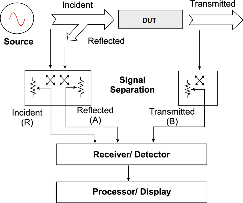
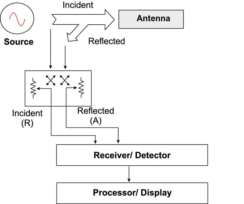
The original image was taken from here and I’ve edited it. Click on the images to view them in larger size.
So, in the first image you see that the VNA has a a signal generator which feeds the device under test (DUT) from one port and then receives the output of the DUT on a second port. Then the VNA is able to measure the incident, reflected and transmitted signal and with some maths can calculate the parameters. The VNA is actually only able to measure the reflection coefficient (S11) which depends on the incident and reflected signal before the DUT; and the transmission coefficient (S21) which depends on the transmitted signal after the DUT. An intuitive way of thinking about this is what happens when you try to fit a hose to a water pump while it’s pumping out water. While you try to fit the hose, if the hose diameter doesn’t fit the pump then part of the water flow will get into the hose and some will spilled out (reflected back?). But if the hose fits the pump perfect then all the flow will go through the hose.
In case of an antenna, you can’t really measure the transmitted energy in a simple way that can be accurate for this kinds of measurements. Therefore, only one port is used and the VNA can just calculate the reflection coefficient. But in most of the times this is enough to get valuable information and be able to trim your antenna. The S11 coefficient is important to calculate the antenna matching and consequently the impedance matching defines if your antenna will be able to transmit the maximum energy. If the impedance don’t match, then your antenna will only transmit a portion of the incident energy.
As I’ve mentioned earlier, the antenna will be affected also from other conditions and not only impedance matching, therefore a portable VNA is really helpful to measure the antenna on site and on different conditions.
For this post, I’m using the new NanoVNA v2 analyzer, which I’ll introduce next.
NanoVNA v2
Until few years ago a VNA was a very expensive and considered as an exotic measurement instrument. A few decades ago a VNA would cost many times your apartment (or house) price and a few years ago many times your yearly salary. Nowadays the IC manufacturing process and technology and the available processing power of the newer small and cheap MCUs, brought this cost down to… $50. Yes, that’s just $50. This is so mind blowing that you should get one even if don’t know what it is and you’ll never use it…
Anyway, this is how it looks like:
There are many different sellers in eBay that sell this VNA with different options. The one I bought costs $60 and also includes a stylus pen for the touch screen, a hard metallic cover plate for top and bottom, a battery, coax cables and load standards (open, close and 50Ω). I’ve also printed this case here with my 3D printer and replaced the metal plates.
As you can see this is the V2, so there has to be a V1 and there is one. The main and most important difference between the V1 and V2 is the frequency range, which in V1 is from 50KHz up to 900MHz and in V2 is from 50KHz up to 3GHz! That’s an amazing range for this small and cheap device and also means that you can measure 2.4GHz antennas used in WiFi. I’m not going to get in more details in this post, but you can see the full specs in here.
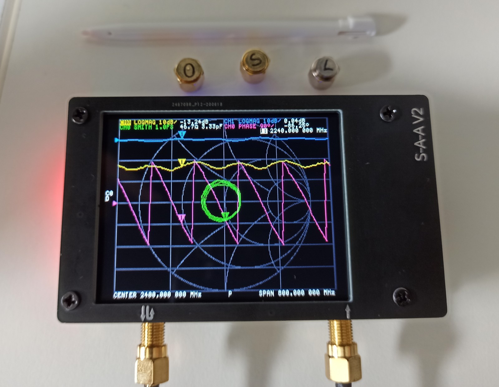
As I’ve mentioned the TFT has a touch controller which is resistive, therefore you need a stylus pen to get precise control. Actually, this display is the ILI9341 which I’ve used in this post a few years back and I’ve managed to get an amazing refresh rate of 50 FPS using a dirt-cheap stm32f103 (blue-pill). As you can see from the above photo, the display is showing a Smith chart and four different graphs. This is the default display format but there are many more that you can get. If you’re interested you can have a look in the manual here.
The graphs have a color coding, therefore in the above photo the green graph is the smith plot, the yellow is the port 1 (incident, reflected), the blue is the port 2 (transmitted) and the green is the phase. In the bottom you can see the center frequency and the span which is this case is 2.4GHz and 800MHz, but depending the mode in bottom of the screen you may see other information. Again, for all the details you can read the manual as the menu is quite large.
My favourite thing about the nanovna v2 is that the firmware is open source and available on github. You can fork the firmware and make changes, build it and then uploaded to the device. The MCU is the GD32F303CC, which seems to be either an STM32F303 clone or it’s a side product from ST with a different part number to target even lower-cost markets. From the Makefile it seems that this MCU doesn’t have an FPU, which is a bit unfortunate as this kind of device would definitely benefit from this. Also from the repo you can see that libopencm3 and mculib are used. One thing that it could be better is CMake support and using a docker for image builds in order to get reproducible builds, which increase stability. Anyway, I’ll probably do this myself at some point.
The only negative I could say for this device is that the display touch-film is too glossy, which makes hard to view under sunlight or even during day inside a bright room. This can be solved, I guess, by using a matte non-reflective film like those ones used in smartphones (but not glass because the touch membrane is resistive).
The antenna
As I’ve mentioned earlier, for this post I’ll only measure an external WiFi antenna which is common in many different devices. In my case this device is the open source TTGO T-Journal ESP32 camera here. This PCB ships with various different camera sensors and it usually costs ~$15. I bought this camera to use it with my 3D printer before I’ve installed octopi and to be honest I may revert back to it because it was more convenient than octopi. I’ve also printed a case for it and this is how it looks.
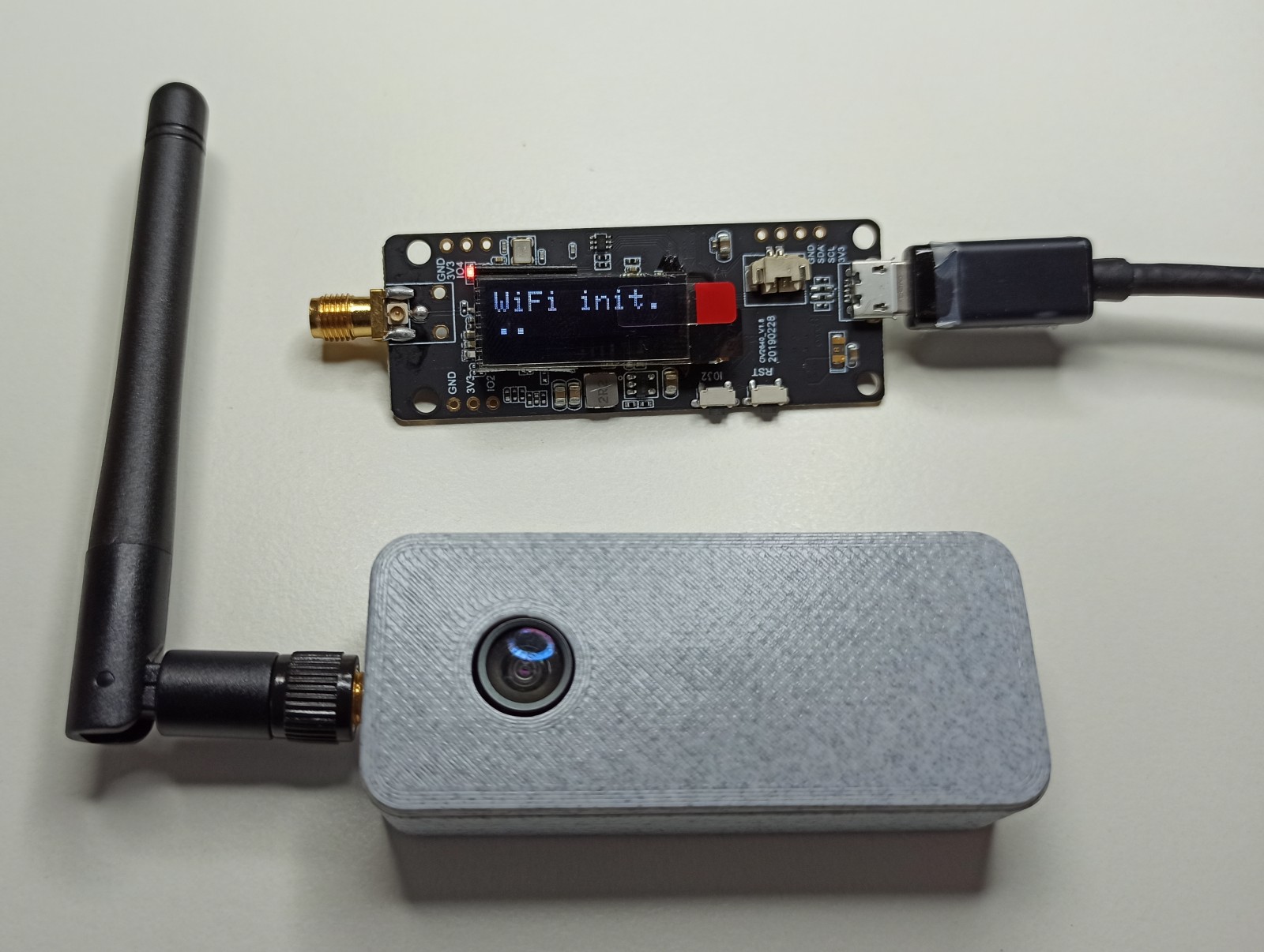
Above is just the PCB module and below is the module inside the case and the antenna connected. This is a neat little camera btw.
As you can guess, those antennas in those cheap camera modules are not meant to be very precise, but they do the job. As a matter of fact, it doesn’t really make sense to even measure this antenna, because for it’s usage inside the house the performance is more that enough. But it would make sense with an antenna that you need to get the maximum performance. Nevertheless, it’s fine to use this for playing around and learning.
This is an omni-directional antenna, which means that it transmits energy like a light-bulb glows light to all directions. This is nice because it doesn’t matter that much how you place the antenna and your camera, but at the same time the gain is low as a lot of energy is wasted. The opposite would be a directional antenna which behaves like a flashlight. The problem with those antennas from eBay is that they don’t came with specs, so you know nothing about the antenna except that it is supposed to be suitable for the WiFi frequency range.
Measurements
OK, now let’s measure this antenna using the nanovna and get its parameters. First thing you need to do before taking any measurements is calibrate the VNA. There are a couple of calibration methods, but the nanovna uses the SOLT method. SOLT means Short-Open-Load-Through and this refers to the port 1 load, therefore you need to run 4 different calibrations, one is by shorting the port, then leave the port open, then attaching a 50Ω load and finally connect port 1 through port 2. After those steps the device should be ready and calibrated. There is a nice video here, that demonstrates this better than I can.
The nice thing is that you can save your calibration data, therefore in my case I’ve set the center frequency to 2.4GHz, calibrated the nanovna and then stored the calibration data in the flash. There are 5 memories available, but maybe you can increase that size in the firmware if needed (that’s the nice thing having access to the code).
These are some things that are very important during calibration and usage:
- Tight the SMA connectors properly. If you don’t do that then all your measurements will be wrong, also if you tight it too much then you may break the PCB connector or crack the PCB and routes. The best way is to use a variable torque wrench, but since this would cost $20-$60, then just better be careful.
- Do not touch any conductive parts during measurements. For example don’t touch the SMA connectors.
- Keep the device away from metal surfaces during calibration.
- Keep the antenna (or DUT) away from metal surfaces during measurements, unless you do it on purpose.
- Make sure you have enough battery left or you have power bank with you.
In the next photo you can see the current test setup after the calibration.
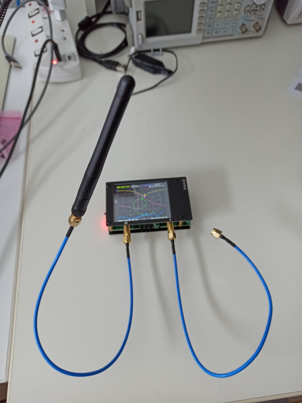
As you can see the antenna is connected on port 1 and I’m running the nanovna with the battery. The next photo is after done with the calibration at 2.4GHz and with the antenna connected.
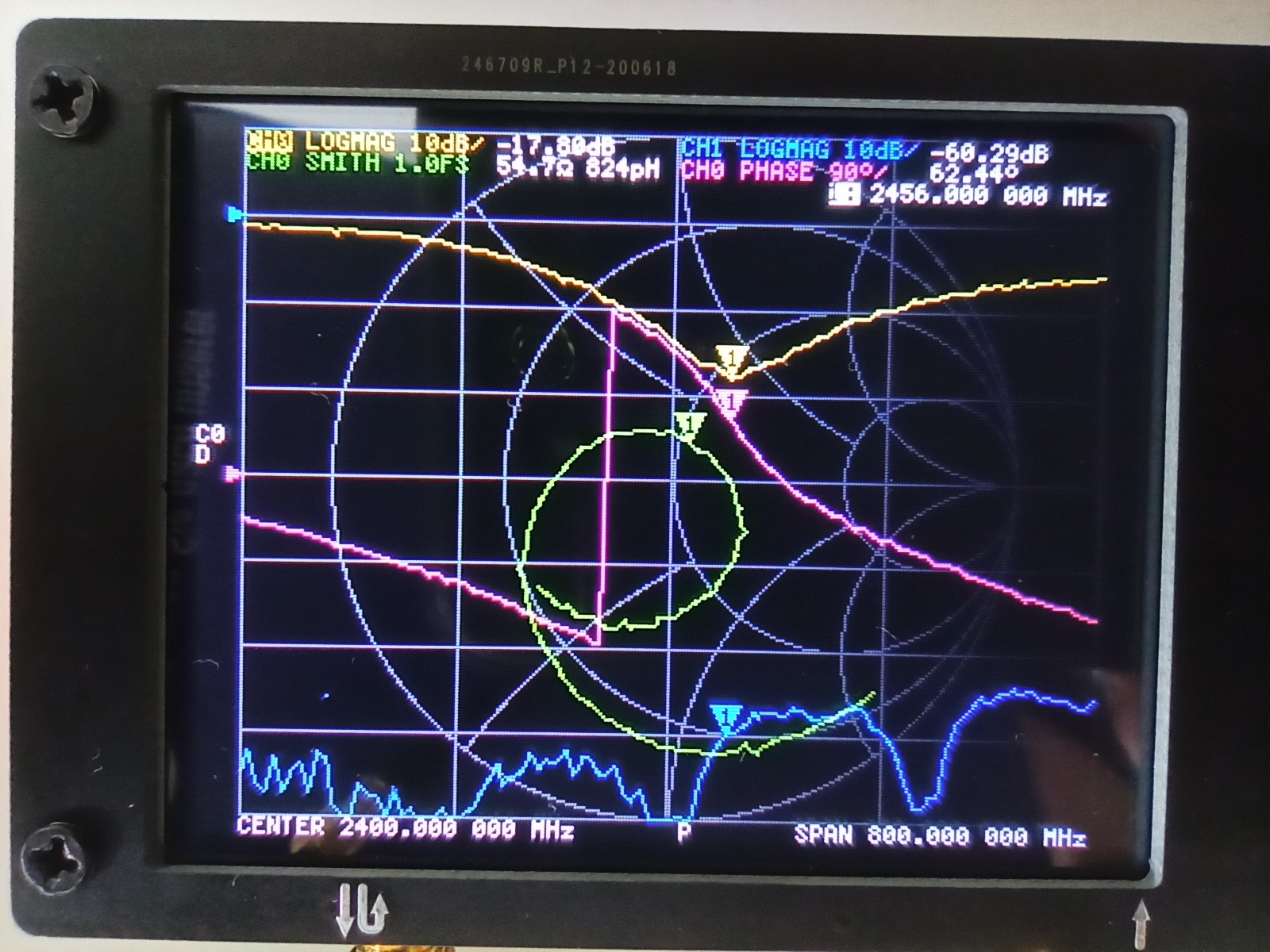
From the above image you see that the antenna resonates at 2456 MHz, which is quite good. From the Smith plot you can see that the impedance doesn’t match perfectly and it’s a bit higher than the 50Ω (54Ω) and also it has a 824pH inductance. That means that part of the incident energy is reflected at the resonance frequency.
Next you can see how the antenna parameters change in real-time when a fork is getting close to the antenna.
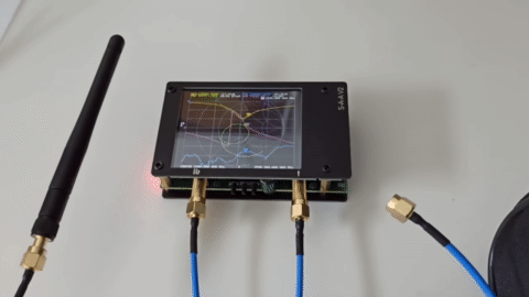
As you can see the antenna is drastically affected, therefore you need to have this in mind. Of course, in this case the fork is getting quite close to the antenna.
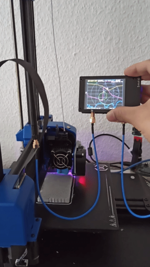
Finally, I’ve used the whole setup near the 3D printer while printing to see how the printer affects the antenna in different positions. As you might be able to see from the following gif, the position does affect the antenna and also is seems that the head movement affects it, too.
Conclusions
I have to admit that although I’m not an RF engineer or experienced on this domain, I find the nanovna-v2 a great device. It’s not only amazing what you can get nowadays with $60, but it’s also nice to be able to experiment with those RF magic stuff. At some point in the future I’m planning to make custom antennas for drones and FPVs and also build my own FPV, so this will certainly be very useful then.
Even if you’re not doing any RF this is a nice toy to play around with and try to understand how it works and also how antennas work and perforn. Making measurements is really easy and being a portable device makes it even better for experimenting. It’s really cool to see the antenna parameters in real time and try to explain what you see on the display.
As I’ve mentioned in the post, this case scenario is a bit useless as the camera just works fine inside the house and also the distance from the wifi router is not that far. Still, it was another stupid-project which was fun and I’ve learned a few new tricks. Again, I really recommend this device, even if you’re not an RF engineer and try to experiment with it. There are many variations and clones in eBay and most of them seem to be compatible with the open source firmware, just be aware that there’s a case that some variations may not be compatible.
Have fun!
Comments powered by Disqus.