EMC probe using RTL-SDR
Intro
This stupid project is a side project that I’ve done while I was preparing for another stupid project. And as it was a fun process, I’ve decided to create a post for it. Although it’s quite amazing, it’s actually quite useless for most of the home projects and completely useless for professional use. Anyway, in the next project I plan to use a 10MHz OCXO as a time reference. The idea was to use a rubidium reference, but it’s quite expensive and it didn’t fit in the cost expectancy I have for a stupid project. Of course, both OCXO and the Rb are enormous overkill, but this is the point of making stupid projects in the first place.
Anyway, a couple of weeks ago I’ve seen Dave’s (EEVblog) video in youtube here. In this video Dave explains how to build a cheap EMC probe using a rigid coax cable, an LNA and a spectrum analyser. So, he build this $10 probe, but the spectrum analyser he used costs lots of bucks already. He mentions of course in the end that he would at some point make a video by using a SDR instead of a spectrum analyser. Well, in my case I needed to measure how my OCXO behaves. Does it leak the 10MHz or harmonics in different places? And if yes, how can I reduce this RF leakage. So, I’ve decided to build an EMC probe myself. And this is what this post is about.
Components
These are mainly two components that I’ve used for this project.
RTL-SDR
The SDR dongle I’ve used is the RTL-SDR. There are a few reasons for this decision, but the most important one is that it goes down to 500KHz without any modification or any additional external hardware. Although the tuner used on the RTL-SDR (which is Rafael Micro R820T/2) is rated at 24 – 1766 MHz, the V3 (3rd revision) supports a mode called direct sampling mode (dsm), which is software enabled and can make the reception under the 24MHz possible. This makes also possible to use it as a spectrum analyser to detect the leakage of the 10MHz OCXO. So, definitely buy this specific dongle from here if you’re interested for this range. Just have in mind that it’s not the intended use of dsm to have high accuracy, but it’s perfectly fine for this case.
This is the dongle:
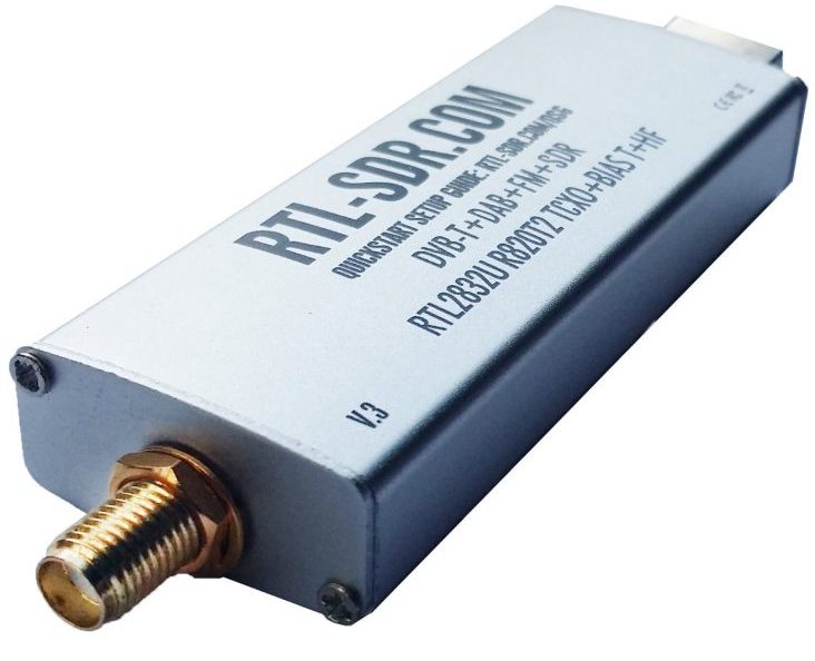
Another reason to buy that specific dongle is to support the RTL-SDR blog the great work that Carl Laufer does (and the great support). In my case, the first dongle I got had a small issue and I’ve just contact Carl and he immediately shipped another unit. Also his book, is excellent for beginners and if you buy the kindle version you get free updates for ever. Great stuff.
Semi-rigid Coax cable
This is the cable that you need to make the probe. Get the 30cm one, so you can make 2 probes. I’ve made a small and big one and the large is twice the size of the small one. This how the cable looks like:
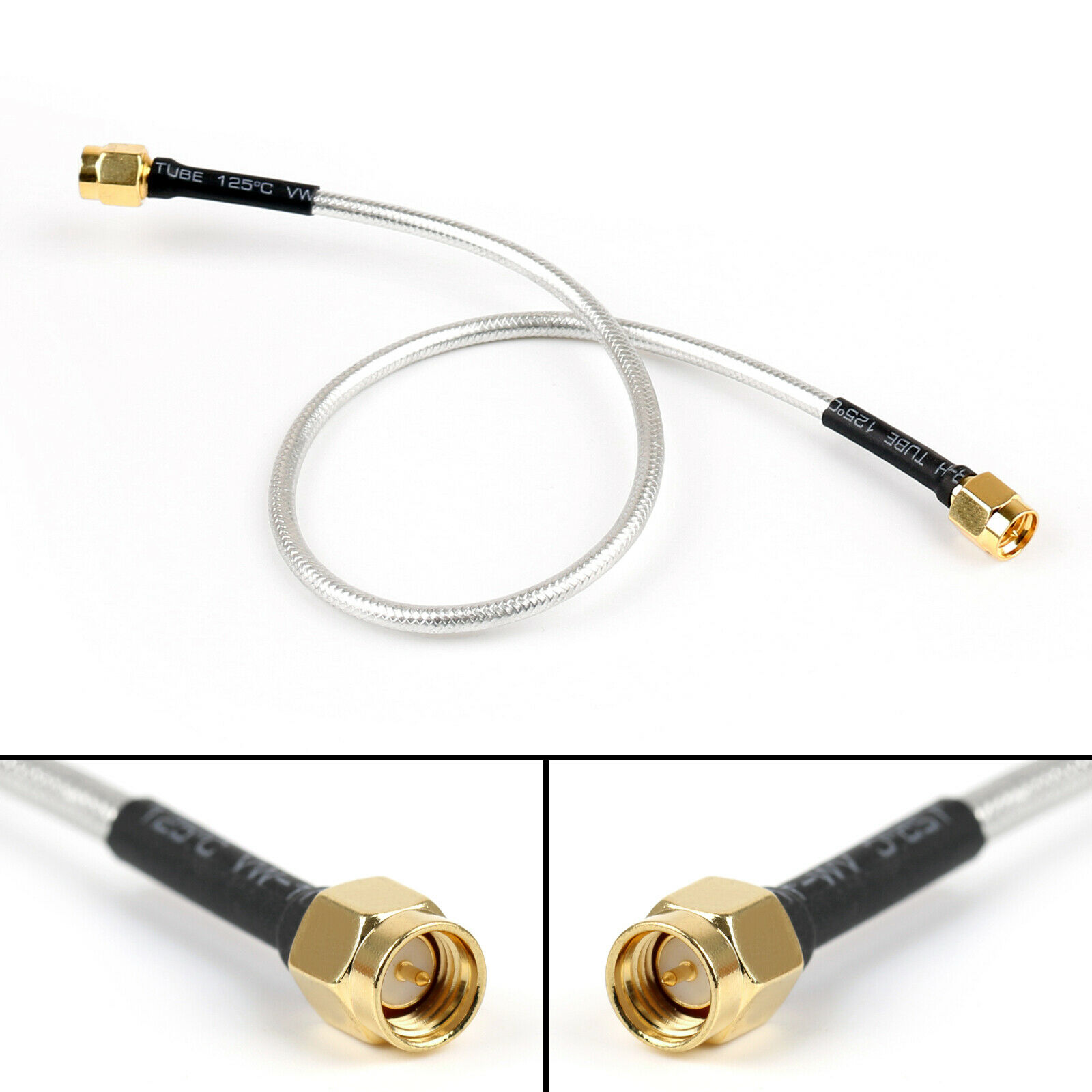
You may also need an antenna cable with an SMA male-female ends. This can be used as an extension to the probe (one of the RTL-SDR options includes that cable). I’ll show you later the two options you have how to use the probe with the rtl-sdr.
Project
Regarding how to make the probe, I think Dave’s video that I’ve linked above, explains everything in great detail; therefore, I will just add my 2 cents from my own experience. Have in mind that those rigid cables are really tough to bend and cut their shielding. I’ve used a thick board marker and a pencil to bend the cables in the two different sizes. Also, in order to cut the shielding and create the gap on the top of the probe (that is explained in the video), you need to make sure that you have a new and sharp blade to your cutter, otherwise it will be really hard and messy. Finally, when you solder the end of the cable to the main cable body to create the loop, first put up you soldering iron temperature (400+ degrees), then put some solder in the tip of the exposed core and use a high temperature resistant glove (or oven glove) to bend, press and hold the end of the cable to touch the rigid shield and solder the tip of the cable to the shielding. Then it will keep its shape and you can have a free hand to finish soldering the rest.
These are my probes after soldering them. 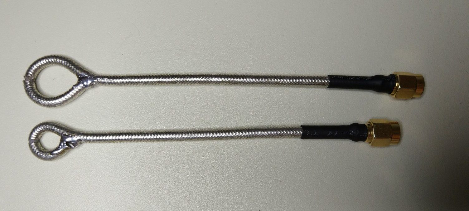
Then I’ve used a black rubber coating paint for insulation on the rigid shield. So this is how the probes are looking now.
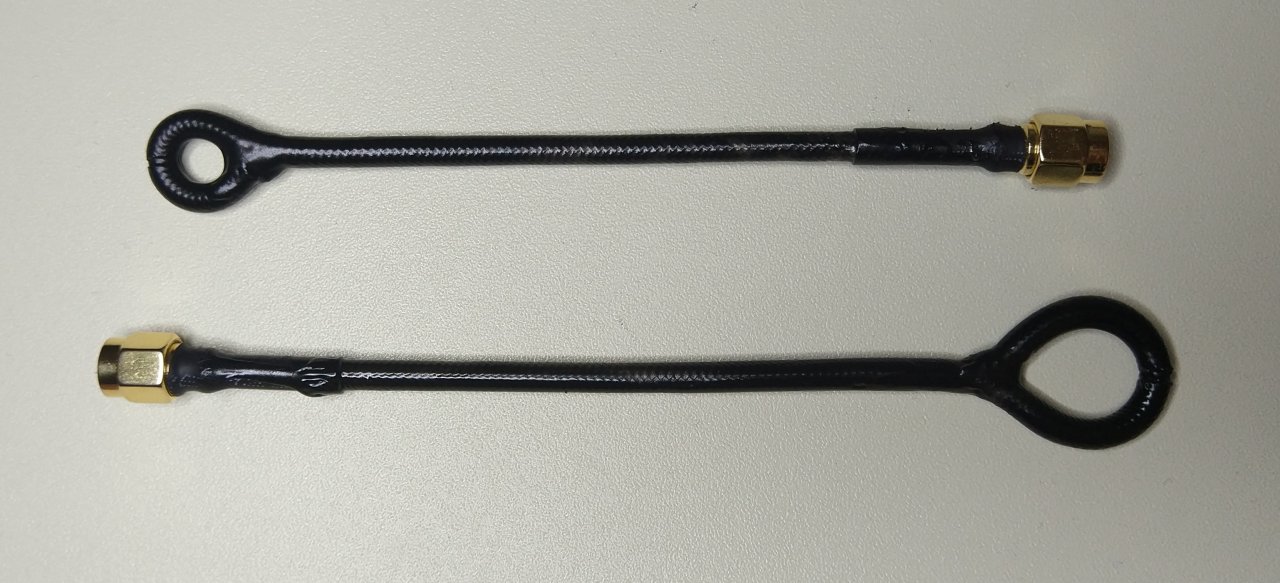
These are diameters of each probe.
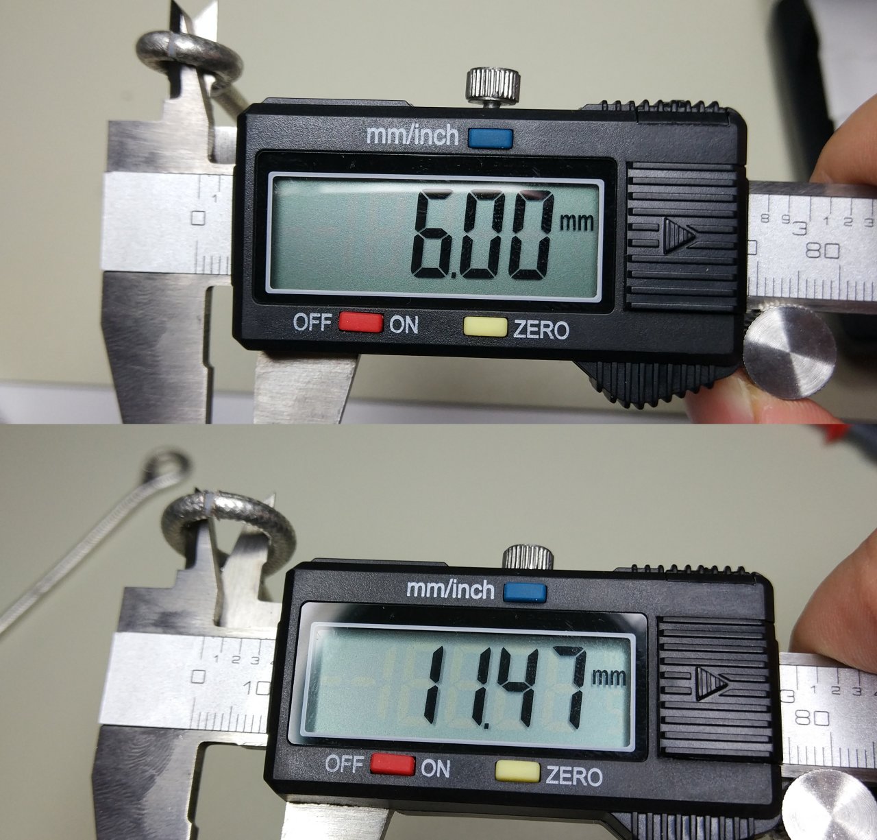
So, the large one has almost the double radius and can also probe twice the area. It would be also nice if the probe end was a true circle (and not elliptic), but for my usage case it works just fine.
Now that you have the probes and the RTL-SDR, there are two ways to use them. One way is to use a USB extension to plug the dongle and then screw the probe straight on it. The other way is to plug your RTL-SDR dongle on a USB port then use an antenna extension cable to connect the probe to the dongle. The next pictures show the two setups.
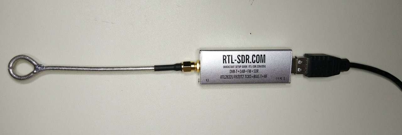

Of course, you can also use the second setup with a USB extension. Anyway, I prefer the first more, because that lowers the interference and signal attenuation as there is no a long cable between the antenna and the dongle. Also the case of the dongle acts like a handle and makes it easier to hold it. It might get a bit warm depending the range you use it, but not that much, though.
Next I’ve tested how much current the RTL-SDR dongle draws when is running in the direct sampling mode (dsm) and it seems that’s not that much actually, so in my case was ~110mA.
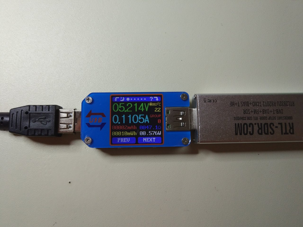
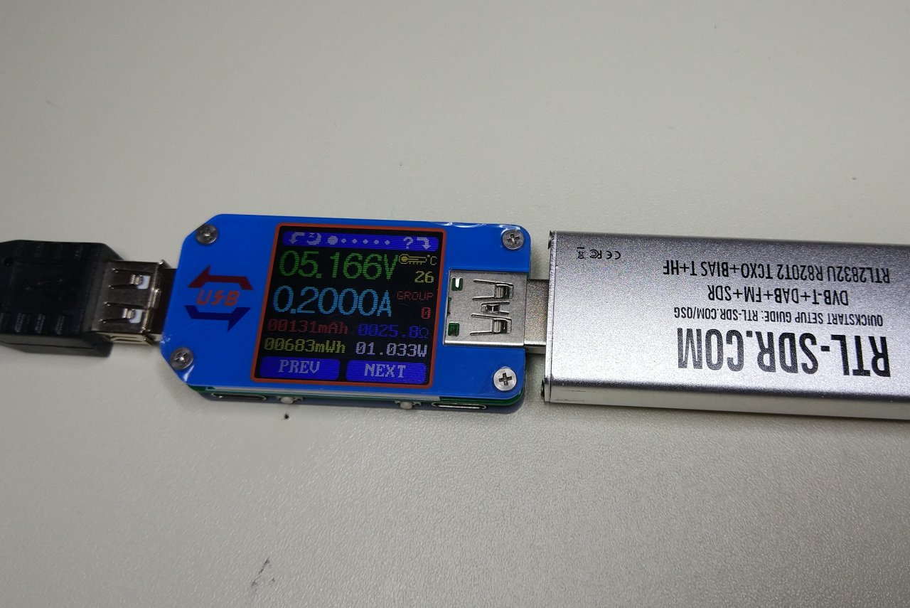
The above one is the replacement dongle. The first dongle was drawing 200mA in the beginning and then this current started to increase more and more, the dongle was burning hot and then at some point it died. But the replacement is working just fine. This is the only picture of the old dongle that I’ve managed to get while it was still working.
Next thing is to select the software that you’re going to use. Since, I’m limited to Linux, I’ve used the SDR# git repo with the mono project run-time. There are a couple of things that you need to do in Ubuntu 18.04LTS in order to make the rtl-sdr work properly.
From now on RTL-SDR or dongle is referred to the hardware and rtl-sdr to the software.
First you need to clone this repo:
https://github.com/osmocom/rtl-sdr
In there you’ll find a file called rtl-sdr.rules. Just copy that to your udev rules and reload.
1
2
3
sudo cp rtl-sdr.rules /etc/udev/rules.d/
sudo udevadm control --reload-rules
sudo udevadm trigger
The above just makes sure that your user account has proper permissions to the USB device in /dev and can use libusb to send commands to the dongle. Then you need to blacklist some kernel modules. In Ubuntu, the rtl-sdr has a module driver as this device is meant to be used a generic DVB-T receiver, but in order to use the device with SDR# you need to disable those drivers and use the rtl-sdr user space drivers. To identify if your distro has those default drivers run this command:
1
find /lib/modules/(uname -r) -type f -name '*.ko' | grep rtl28
In my case I get this output.
1
2
3
4
/lib/modules/4.18.20-041820-generic/kernel/drivers/media/usb/dvb-usb-v2/dvb-usb-rtl28xxu.ko
/lib/modules/4.18.20-041820-generic/kernel/drivers/media/dvb-frontends/rtl2832_sdr.ko
/lib/modules/4.18.20-041820-generic/kernel/drivers/media/dvb-frontends/rtl2832.ko
/lib/modules/4.18.20-041820-generic/kernel/drivers/media/dvb-frontends/rtl2830.ko
So, I had to blacklist the modules. To do that in ubuntu create this file /etc/modprobe.d/blacklist-rtlsdr.conf and add these lines in there.
1
2
3
4
/lib/modules/4.18.20-041820-generic/kernel/drivers/media/usb/dvb-usb-v2/dvb-usb-rtl28xxu.ko
/lib/modules/4.18.20-041820-generic/kernel/drivers/media/dvb-frontends/rtl2832_sdr.ko
/lib/modules/4.18.20-041820-generic/kernel/drivers/media/dvb-frontends/rtl2832.ko
/lib/modules/4.18.20-041820-generic/kernel/drivers/media/dvb-frontends/rtl2830.ko
You might have to reset your system to check that this works properly. Now you can build the rtl-sdr repo and test the module. To do that
1
2
3
4
5
6
git clone git@github.com:osmocom/rtl-sdr.git
cd rtl-sdr/
mkdir build
cd build/
cmake ../
make
Then the executable is located in the .src/ folder. Have in mind that this step is not really needed to run SDR#, but it’s good to be aware of it in case you need to test your dongle before you proceed with the SDR#. Now, to install SDR# in Ubuntu do this:
1
2
3
4
5
6
7
8
sudo apt install mono-complete libportaudio2 librtlsdr0 librtlsdr-dev
git clone https://github.com/cgommel/sdrsharp
cd sdrsharp
xbuild /p:TargetFrameworkVersion="v4.6" /p:Configuration=Release
cd Release/
ln -s /usr/lib/x86_64-linux-gnu/libportaudio.so.2 libportaudio.so
ln -s /usr/lib/x86_64-linux-gnu/librtlsdr.so.0 librtlsdr.dll
mono SDRSharp.exe
If you have your dongle connected then you can start play with it. For more details on how to use SDR# with the dongle, you better have a look to Carl’s book or have a look to the rtl-sdr blog as there are some posts that have info about it.
In my case I needed to use the direct sampling mode, so I’ve selected the RTL-SDR / USB device and then clicked configure and from the new dialog that opens select the Direct sampling (Q branch) option in the Sampling Mode. This will work only in the V3 of the RTL-SDR dongle! If you following these steps, now close the dialog box and check the Correct IQ checkbox, drag the audio AF Gain to zero (you don’t need audio feedback) and then you’re ready. I like to lower down the contrast slider in the right so the waterfall is a bit more deep blue as the noise is gone. Also I uncheck the Snap to grid.
In case that you have an older version of the RTL-SDR, or another dongle then you need to do a small modification to get it working in the direct sampling mode, but you need to google it, depending your dongle.
Testing the probes
For the tests, I’m going to use a cheap second-hand OCXO that I’ve bought from ebay and it’s made from Isotemp and the model number is OCXO143-141. This is the one:
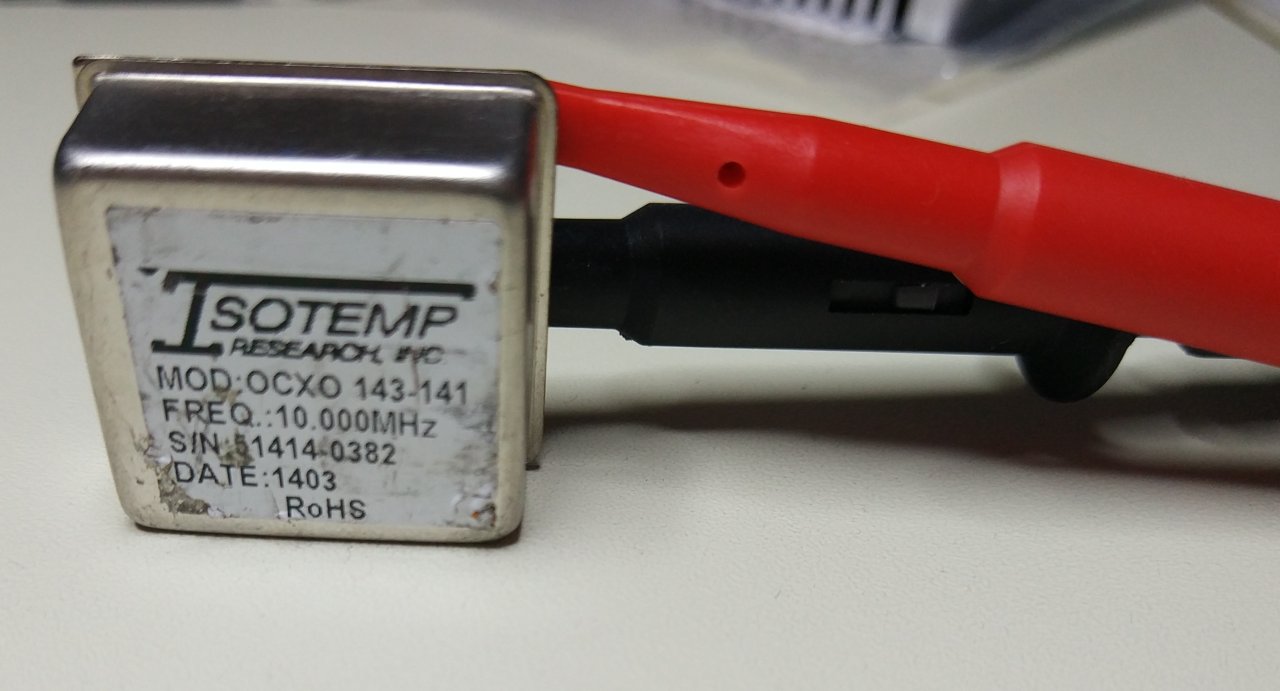
This seems to be a customised OCXO as there’s no reference for it in the official cmpany site. There is a 143-XXX series but not 143-141 model. Anyway, from the PDF file here, it’s the A-package. I’m not going to go into the details, but it’s an amazing OCXO for the price and you can find it very cheap in ebay. I got mine for 16 EUR. Its frequency output is 10MHz and as I’ve said earlier that’s lower than the minimum supported frequency from most of the SDR dongles, but the RTL-SDR can go down to this frequency when is set to direct sampling mode.
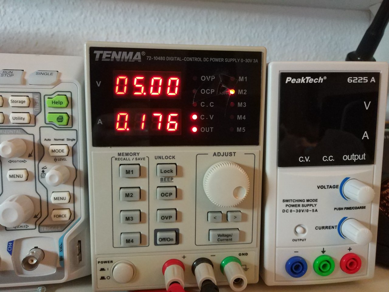
As you can see from the above image, you just need to connect the GND and the +5V and that’s it. Normally, the OCXO needs approx. 5 mins to stabilise, because the heating element needs some time to warm up the case and the crystal inside it to the operating temperature which is 70 ºC. Hence, be aware not to touch it after some time, because it might be very warm. When the OCXO is connected to the power supply then it draws ~500mA current @ 5V for a few seconds, but after that gradually drops and it’s stable at approx 176 mA.
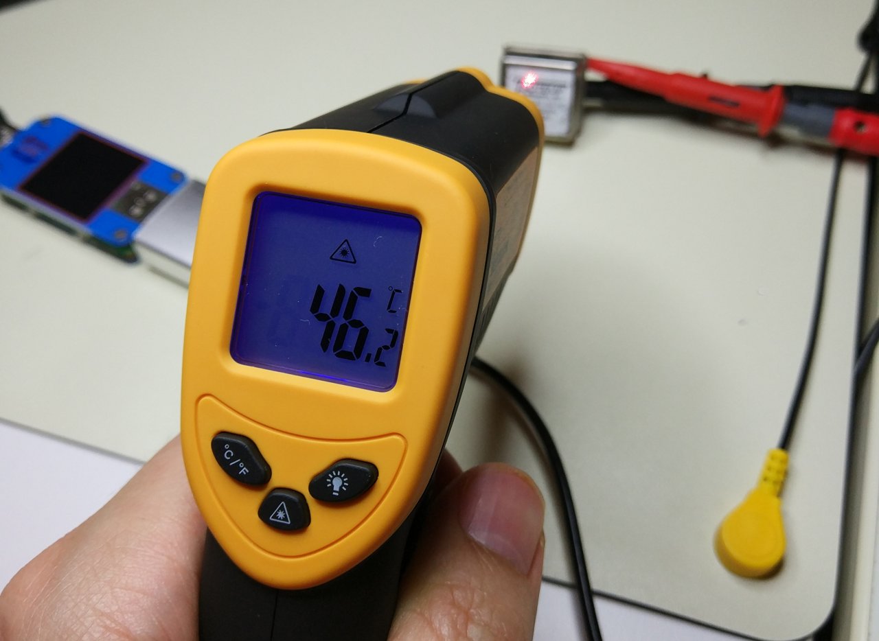
The temperature of the case was around 46 ºC, but with a lot of variation, so I guess that’s because of the reflective case, which makes difficult for my IR temperature gun to measure the temperature precisely.
Ok, so now that everything is set, lets test the probes.
I’ve used the USB extension to connect the dongle to my Ubuntu workstation and I’ve connected the probe on the dongle’s RF input. Then I’ve build the sdrsharp from the git source (I’ve explained the process earlier) and run the GUI. Selected the the RTL-SDR / USB, configured the sample rate to 2.4MSPS and the sampling mode to Direct sampling (Q branch). Then checked the Correct IQand unchecked the Snap to grid and pressed Play. Simple.
This is the capture I’ve made when I’ve put the probe close to the 10MHz output of the OCXO.

So, it works!
After that I’ve used to probe on the PSU cables that was powering the OCXO and I’ve seen that the 10MHz was leaking back to the PSU. Also the leak was not allover the cable but in some spots only. In my use case I’ll use a USB cable to power up the OCXO that will also power the rest circuit; therefore I’ll probably need some ferrite core cable clips, which I’ve already have ordered as I was expected that, but it will take some time to get them from China. Anyways, that’s also a topic for the next project, but I need the probe to at least minimise this leak.
Limitations and comparisons
Now I’ll try to guess how this DIY EMC probe using the RTL-SDR dongle compares to a spectrum analyser with proper EMC probes and then try to test the diy probes with my Rigol DS1054Z, which has an FFT function. The list might not be complete as I don’t know all the specific details and I’m pretty much guessing here.
| Professional probe | DIY probe |
|---|---|
| [+] It’s calibrated | [+] Very cheap to make |
| [+] Just buy it and plug it in | [+] If you don’t care for accuracy it’s fine |
| [+] Well defined characteristics | [+] Fun to make one |
| [-] High price | [-] You need to build it by your self |
| [-] No fun making it | [-] Not calibrated |
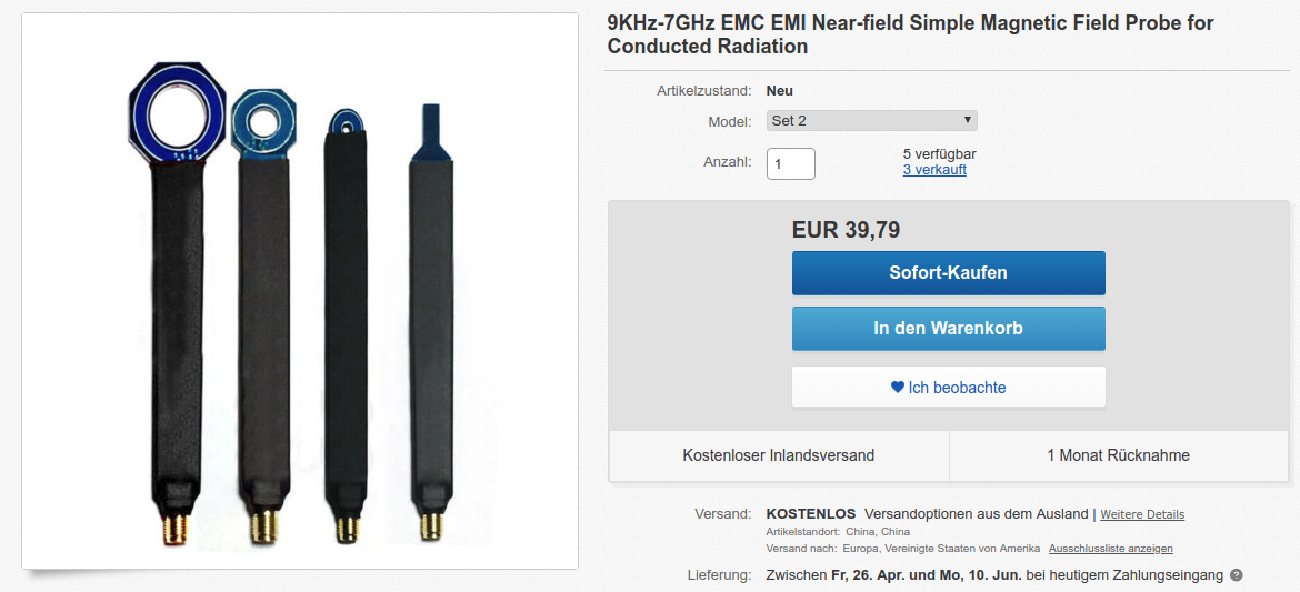
You can also buy a cheap set of EMC probes on ebay, of course. That costs around 40 EUR which is that’s not too much if you want to get a bit more serious or want to avoid the hassle to create your own probes. It’s not in my plans to buy something like that, because I don’t need better accuracy or calibrated probes, I just need to be able to see if there’s a frequency there and for that purpose the DIY probe is more than perfect.
OK, so now let’s see how the RTL-SDR dongle compares to a spectrum analyser. Again, these are more guesses as I don’t have a spectrum analyser and I’m not expert in the field.
| Spectrum Analyzer | DIY probe |
|---|---|
| + Wider real-time bandwidth | + OK’ish real-time bandwidth |
| + Very low noise | + OK’ish in terms of noise |
| + Tons of options and functions | + You can write your own functions using the rtl-sdr API and hack it |
| + Wider range (several GHz but for more $$$) | + Very, very cheap |
| – Much more expensive | + Portable (can be used even with your phone) |
| – Less portable | – Limited real-time bandwidth |
| – Can’t hack it | – Can’t be used when accuracy is needed |
Depending the money you spend you can get very expensive spectrum analysers that include amazing functionality. There are also spectrum analysers for hobbyists and amateurs (like the Rigol DSO700 series), but they cost from 750 (for 500MHz) up to 1100 EUR (for the 1 GHz). That’s a lot of money for a hobbyist! You can spend just 25 EUR for the RTL-SDR dongle and buy something else with the rest…
If I had to choose which is the most significant difference, I would probably say it’s the real-time bandwidth. For example, by using the RTL-SDR dongle you’re limited in approx. 2MHz bandwidth real-time processing of data chunks. With a spectrum analyser the real-time bandwidth can be up to 10-25MHz (or more). I know that the RTL-SDR dongle documentation is clear regarding the real-time bandwidth and it mentions that the max bandwidth is 1.6MHz (due to Nyquist) and the 3.2MSPS or 3.2MHz is by using the I/Q samples. On the other hand, I don’t know if the spectrum analyser specs are referring to Nyquist bandwidth or not. They may do, I don’t know, but nevertheless is higher bandwidth in any case. Do you really need it though? In that price?
The key point here is that for an amateur (or even professionals sometimes), it doesn’t really matter if what you see in the screen is 100% accurate. Most of the times you just want to see if there’s something there and if there’s a frequency in that bandwidth that pops up. So with the RTL-SDR dongle you may not get an accurate value of the magnitude of the frequencies that you see and also more noise, but at least you can see that there is a frequency popping up in there.
Comparing with the FFT function of the DS1054Z
In order to compare the RTL-SDR and sdrsharp and the FFT function of the DS1054Z I can’t use the OCXO module as it’s too weak. So in this case, I’ve used the Siglent SDG1025 function generator, which is famous for not being a great performer, but still is just fine for any home project that I’ve done or I may do in the future. I’ve set the output to 10MHz and 1Vpp and then used my ds1054z to capture the output and use the FFT math function and at the same time I’ve used the DIY EMC probe to check what it captures from the SDG1025 cable.
Note: with the probe not connected I’ve an interference at ~9.6MHz, which I don’t know where it comes from, but I have a guess. It’s a lower frequency compared to the internal 28.8MHz TXCO used to clock both the RTL2832U and R820T2. My guess is that it’s a mirror image from the internal 28.8MHz TXCO, because
28.8/9.6 = 3, which is an integer. Btw, also the 48MHz freq of the USB may show an image at 9.6MHz, because28*2 = 48/9.6 = 5. This is there even without the probe connected, so this makes me think it’s because of the TXCO. Anyway, it’s always a good thing to check first without the probe connected, to see if there are any frequencies already in the spectrum you’re interested.
This is what I’ve got without the probe connected:
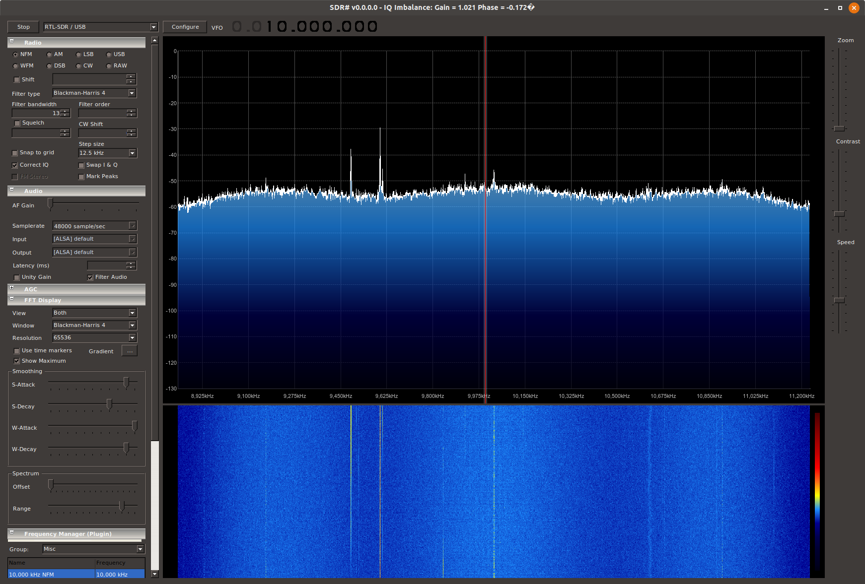
You see the 9.6MHz in the left side. Here you see that there is also one in 9.490MHz, without the probe connected. I can’t figure out where that comes from, because it’s near the 9.6 it’s a bit weird, but the TXCO is 1ppm, which means that even if it was coming from there 1ppm @ 28.8MHz means 28.8Hz and that means that the worst case is to had am image at 9.599MHz. Maybe there’s some internal PLL in the RTL2832U to get the 48MHz (I couldn’t find the datasheets to figure this out) and it has a large offset? Nah, anyway… It’s just there.
Then the next picture is with probing the 10MHz output of the SDG1025 with the RTL-SDR dongle.
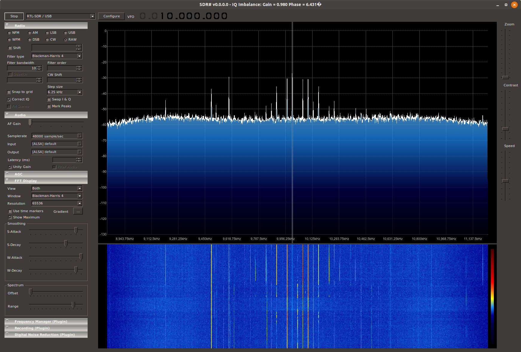
Now you can see that there are quite a few frequencies around the 10MHz. The SDG1025 is set to output a sine! It seems that the sine output of the function generator contains a lot of harmonics that also emit and the probe can capture them. In case of the OCXO I didn’t saw the other spikes although the ouyput is a square wave. Probably because the output of the OCXO was much weaker.
The next picture is the FFT output of the ds1054z.
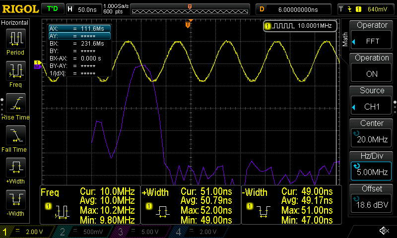
Here you can see that also the FFT of the Rigol shows that there are other frequencies around the 10MHz sine and also the freq counter shows that the output is not very stable. Probably that’s true as I didn’t wait for a long time for the function generator to settle. Btw, as I have the 10MHz OCXO, maybe I’ll use it as an external reference to the SDG1025. This would make it much, much better in terms of output stability (marked as a future project).
Another thing that deserves mention here is the bandwidth of the FFT on the Rigol. In this case I’ve set the FFT mode from trace to *memory in the FFT menu. That makes the screen update much slower (who cares), but you get a wider bandwidth. Also notice that the visible bandwidth here is 5MHz/Div, so you see actually see 50MHz bandwidth on the screen.
Also, it worth mention that the RTL-SDR has much better resolution compared to the Rigol. That’s expected because the bandwidth is smaller and that’s why you see the several spikes around 10MHz in case of the dongle and only a single lobe on the FFT of the Rigol.
Now have a look at this weird thing:
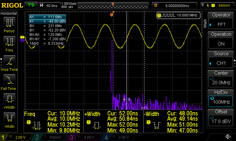
Here you see that the bandwidth is 100MHz/Div, which I dunno, it doesn’t make sense, since this is a 50MHz oscilloscope (with the 100MHz hack, of course) and the displayed spectrum now is 600MHz. So, yeah…. I don’t know what’s going on in here, maybe I’m missing something, but I just guess that it’s because the FFT is just a mathematical function, so although there’s no real input data on the oscilloscope the display just shows the maths results.
Conclusions
First, I really loved the RTL-SDR dongle. Although I was aware of it for some years now, I never had any excuse (or time) to play with it. I’m lucky though, because now it’s much more mature in both hardware and software terms. The RTL-SDR V3 is awesome, because of the software enabled direct sampling mode that allows it to go below the 24MHz and also the rtl-sdr API is more mature/stable and also supports the direct sampling mode setting, too.
Now that I’ve spent some time with the rtl-sdr and I’ve seen the API, I’m really intrigued to use one of the many SBCs that I have everywhere around my workbench to build a standalone spectrum analyser. I’ve seen that there’s already a project for the beaglebone black which is called ViewRF. This is actually a Qt4 application that uses the rtl-sdr API and then it draws on a canvas without the need of a window system as it uses the QWS (Qt Window System). There are a few problems with that, though. First it’s a quite old Qt version (which is fine), but I prefer to use the meta-qt5 layer to build my custom Yocto distros. For example, I already have the meta-allwinner-hx and meta-nanopi-neo4 layers that I could use to build a custom image for one of the supported boards. Those layers are supporting the Qt5 API, but the QWS was removed in that version and that means that I would need to write a new app to do something like the ViewRF. Anyway, I need to investigate a bit more on this, because there probably others that already implemented those stuff long time ago.
I’m also thinking to write an app for one the WiFi enabled SBCs that will run an http server and serve a GUI using websockets to send the data. I don’t know yet the amount of data that are coming from the dongle, so that might not work. Anyway, so many nice stuff to do and so many ideas, but no much time :/
For now, I just want to finish reading Carl’s book as there’s a ton of interesting information in there and is written in a way that really gets you into it. I may not have the time to do a lot of stuff with the RTL-SDR dongle in the future, but nevertheless I want to learn more about it and have the knowledge in the back of my head for future projects and it’s good to know what it can do with it and how it can be used. Still, the EMC probe with a standalone spectrum analyser is a nice project and I will do it at some point in the future. I’ve also found this interesting Yocto layer here. So many cool stuff, so less time.
Have fun!
Comments powered by Disqus.