Hacking a Sonoff S20 and adding an ACS712 current sensor
Intro
Warning! This post is only meant to document my work on how to hack the Sonoff S20. This device is connected directly to 110/220V and if you try to do this your own you risk your own life. Do not attempt to open your device or follow this guide if you’re not also a trained electronic or electrical engineer.
It’s being quite some long time since I’ve hacked a device for the blog This time I’ve did this hack mainly for the next post of the Using Elastic stack (ELK) on embedded In both the previous posts I’ve used a Linux SBC that runs an Elastic Beat client and publishes data to a remote Elasticsearch server. But for the next (and maaaybe the last) post I want to use an example of a baremetal embedded device, like the ESP8266. Therefore I had two choices, first to just write a generic and simple firmware for an ESP module (e.g. ESP-01 or ESP-12E) or even better use an actual mainstream product and create an example of a real IoT application.
For that reason I’ve decided to use the Sonoff S20 smart socket that I’m using to turn on/off my 3D printer. Smart socket just means a device with a single power socket and an internal relay that controls power on the load and in this case the relay is controlled by an ESP8266. In my case, I’m using a raspberry pi 3 running Octopi and both the printer and the RPi are connected on a power socket which is connected on the S20. When I want to print then I turn on the socket using my smartphone and the RPi boots and the printer is turned on. When the printing is done then, the octopi sends a termination message to the S20 and it shuts down. Then after 20 seconds the S20 has received the message is turns off the power on everything.
The current setup doesn’t make much sense to use it with Elastic stack, so I’ve decided to add a current sensor in the Sonoff S20 and monitor the current that the printer draws. Then publish the data to the Elasticsearch server.
I’ve also decided to split the hacking from the rest ELK part, so I’m making this post here to document this hack. Again, I have to tell you not to try this yourself if you’re not a trained professional.
Components
Sonoff S20
According to this wiki, the Sonoff S20 is a wifi wireless smart socket that can connect any home appliances and electric devices via WiFi, allowing you to remote control on iOS/Android APP eWeLink. The device looks like this

Since this device is using an ESP8266, then it’s hack-able and you can write and upload your own firmware. There are also many clones and to be honest it’s difficult to know if you buy an original or a clone, especially from eBay. The schematics are also available here. The most known firmware for the Sonoff S20 is the open source Tasmota firmware that you can find here. Of course, as you can guess, I’m using my own custom firmware because I need to do only some basic and specific stuff and I don’t need all the bloat that comes with the other firmwares.
ACS712
The ACS712 is a fully Integrated, Hall Effect-Based Linear Current Sensor IC with 2.1 kVRMS Isolation and a Low-Resistance Current Conductor. Although this IC only needs very few components around it, you can find it really cheap in eBay in a small PCB factor, like this one here:
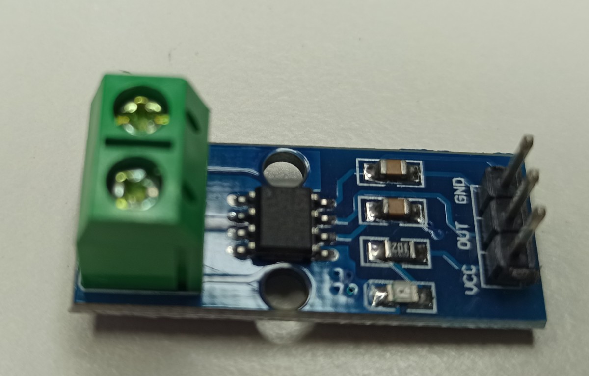
This IC comes in 3 flavors, rated at 5A, 20A and 30A. I’m using the 5A which means that the IC can sense up to 5A of AC/CD current and converts the input current in voltage with a 185 mV/A step. That means that 1A of 220VAC is 185mV and 5A is 1V.
The ugly truth
OK, here you might think that this is quite useless. Well, you’re right, he he, but it’s according to the blog’s specs, so it’s good to go. For those who wonder why it’s useless, the reason is that the 185 mV/A sensitivity of the ACS712 means that the range of 5A is only 925mV. Since the range is -5A to 5A then according to the IC specs it means that the output is from ~1.5V for -5A, 2.5V for 0A and up to ~3.5V for +5A.
Also, the ESP8266 ADC input is limited by design to 1V maximum, but at the same time the noise of the ESP8266 ADC is quite bad. Therefore, the accuracy is not good at all and also when it comes to AC currents 1A means 220VA and 5A (=1V out) means 2200VA, which is extremely high for a 3D printer consumption, which is ~600W max with the heat-bed at max temperature. So, the readings from the ACS712 are not really accurate. But they are enough to see what’s going on.
Also, have in mind that with the ACS712 you can only measure current and this is not enough to calculate real consumption as you need also the real value of the VAC on your socket, which is not 220V and actually fluctuates a lot. Ideally you should have another ADC to measure the output of the transformer which is relative to the AC mains and use this value to calculate real power.
Nevertheless, it’s fun to do it, so I’ll do it and use this device in the next post to publish the ACS712 readings to the Elasticsearch server.
Hacking the Sonoff S20
Well, hacking sounds really awesome, but in reality it was too easy to even consider it as hacking, but anyway. Do, first problem I faced was that the ESP8266 is a 3V3 device and the ACS712 is a 5V device. Also the ACS712 is one of those 5V rated devices that indeed doesn’t work with 3V3. Therefore, you actually need 5V, but the problem is that there isn’t any 5V on the circuit.
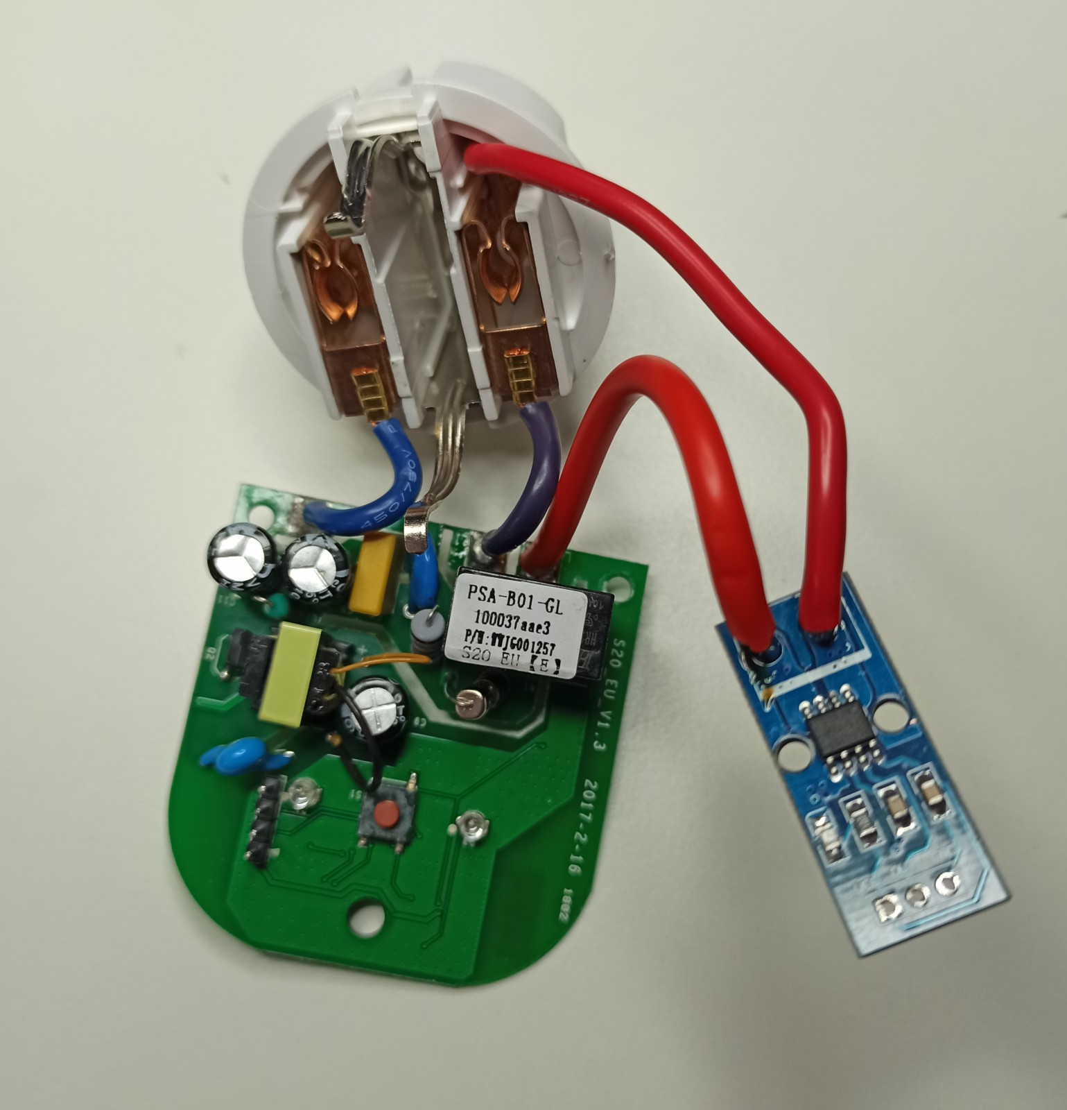
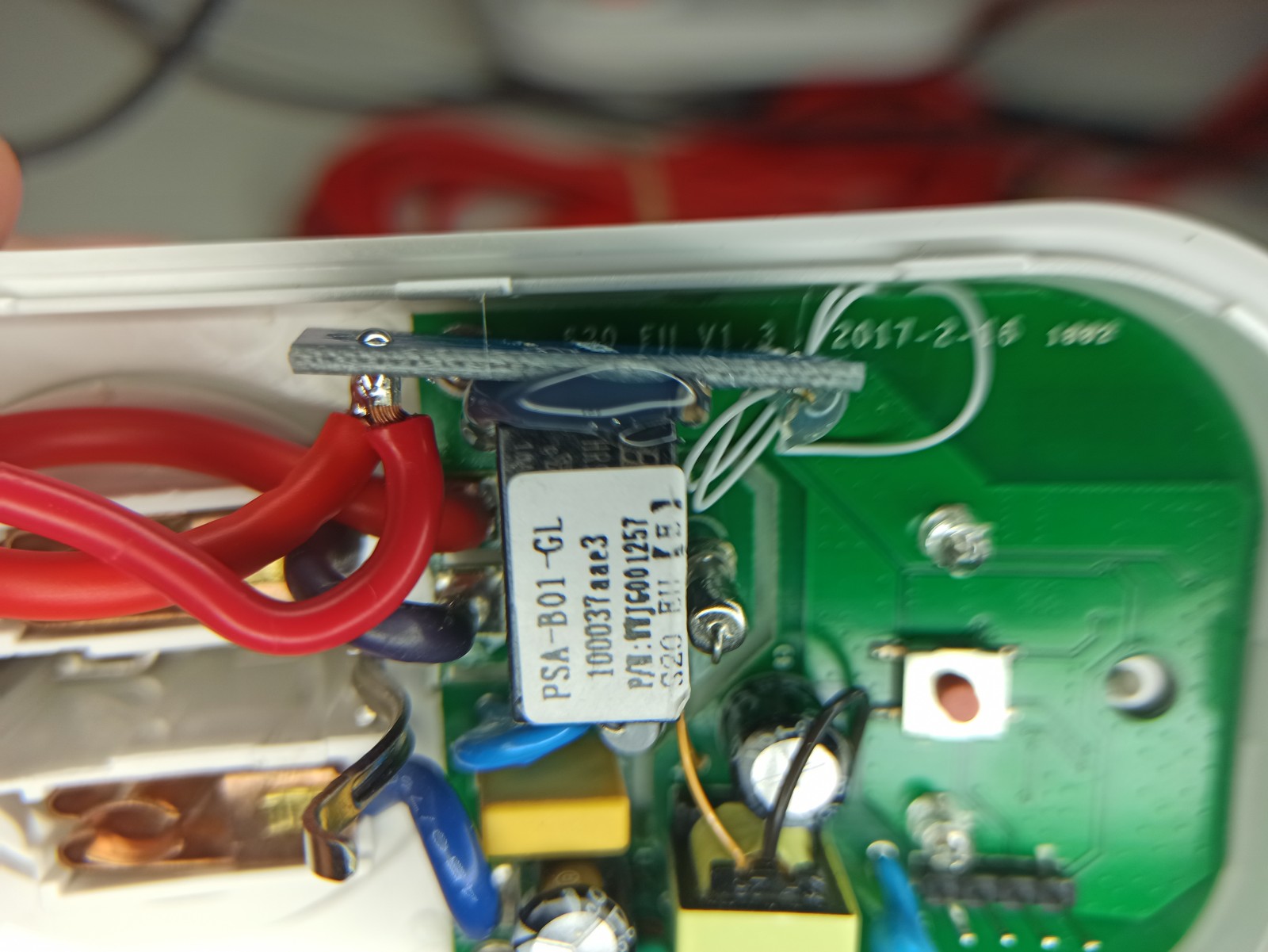
First let’s have a look on my bench.
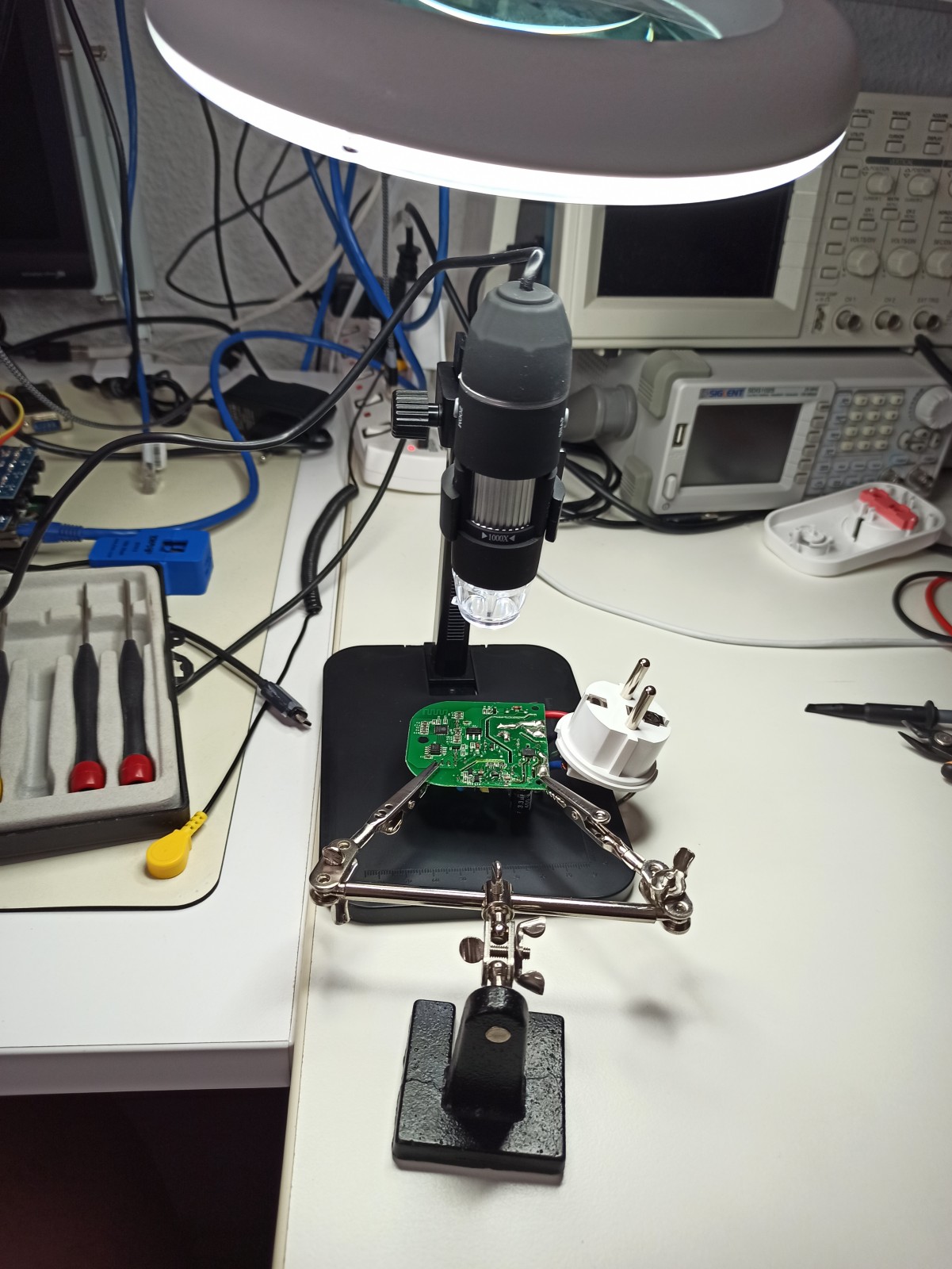
I’ve used a USB microscope to check the board and also make some pictures, but those cheap microscopes are so crap that in the end I’ve just used the magnify lamp to do the soldering…
As you can find out from the schematics here, there is a 220V to 6.2V transformer on the PCB and then there’s an AMS1117-3.3 regulator to provide power to the low voltage circuit.
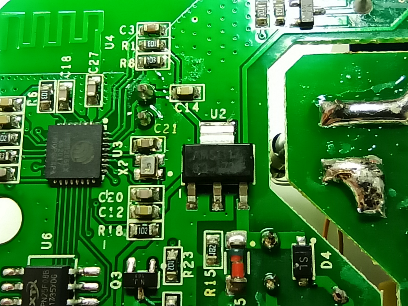
Therefore in order to provide the 5V I’ve soldered an AMS1117-5 on top of the 3V3 regulator. https://www.stupid-projects.com/wp-content/uploads/2020/09/sonoff-5v-reg-on-the-3v3.jpg 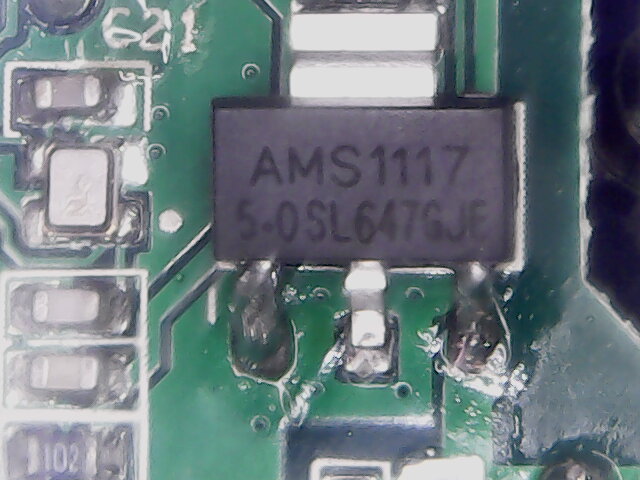
That’s it, an AMS1117 sandwich. OK, I know, you’re thinking that this is a bad idea because now there’s no proper heat dissipation from the bottom regulator and it’s true. But I can live with that, as the heat is not that much. Generally though, this would be a really bad idea in other cases.
Next thing was desoldering the load cable (red) from the PCB and solder it on the IP+ pin of the ACS712 and then solder an extension cable from the IP- to the PCB.
Then I’ve removed the green block connector and the pin-header from the ACS712 PCB so it takes as much less space as possible and then I’ve soldered the GND and the 5V.
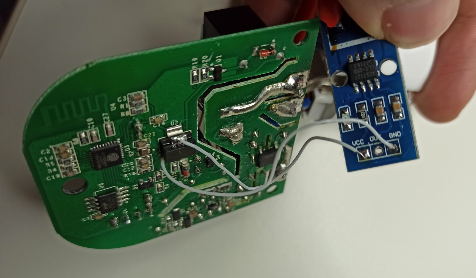
In this picture the regulator sandwich is also better visible. I’ve used a low resistance wire wrapping wire.
Next problem was that the ADC input on the ESP8266 is limited to a max 1V and the output of the ACS712 can be up to 3.5V (let’s assume 5V just to be sure in any case). Therefore, I’ve used a voltage divider on the output with a 220Ω and 56Ω resistors, which means at 5V I get 1.014V. For that I’ve used some 0805 1% SMD resistors and I’ve soldered them on the ACS712 PCB and I’ve solder a wire between them.
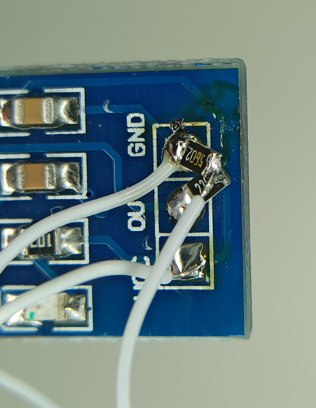
Then I’ve used a heated silicone gun to create a blob that holds the wires and prevent them from breaking.
Then I guess the most difficult thing would probably be to solder the wire from the voltage divider to the ADC pin of the ESP8266, because the pin on the IC is barely visible. Although I’m using a quite flat and big soldering tip on my weller, the trick I do is to melt just a bit solder on the wire end, then place the wire on the pin and finally touch it quite fast with the solder iron tip. I can’t really explain it more, but anyway for me it works fine.
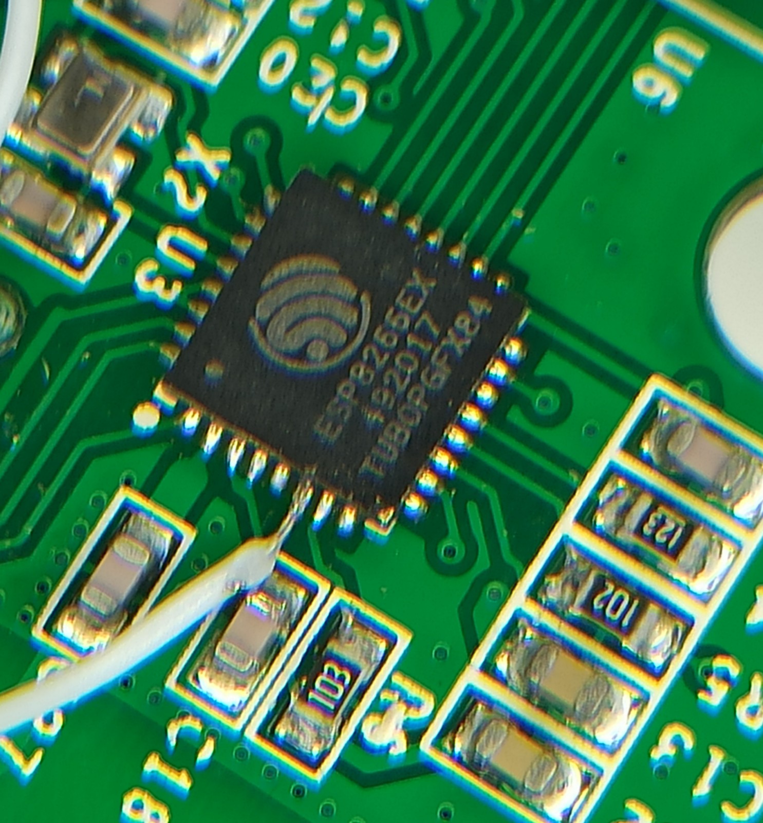
That’s quite clean soldering. Then I’ve used some hot silicone glue to attach the ACS712 PCB on the relay so it doesn’t fly around the case.
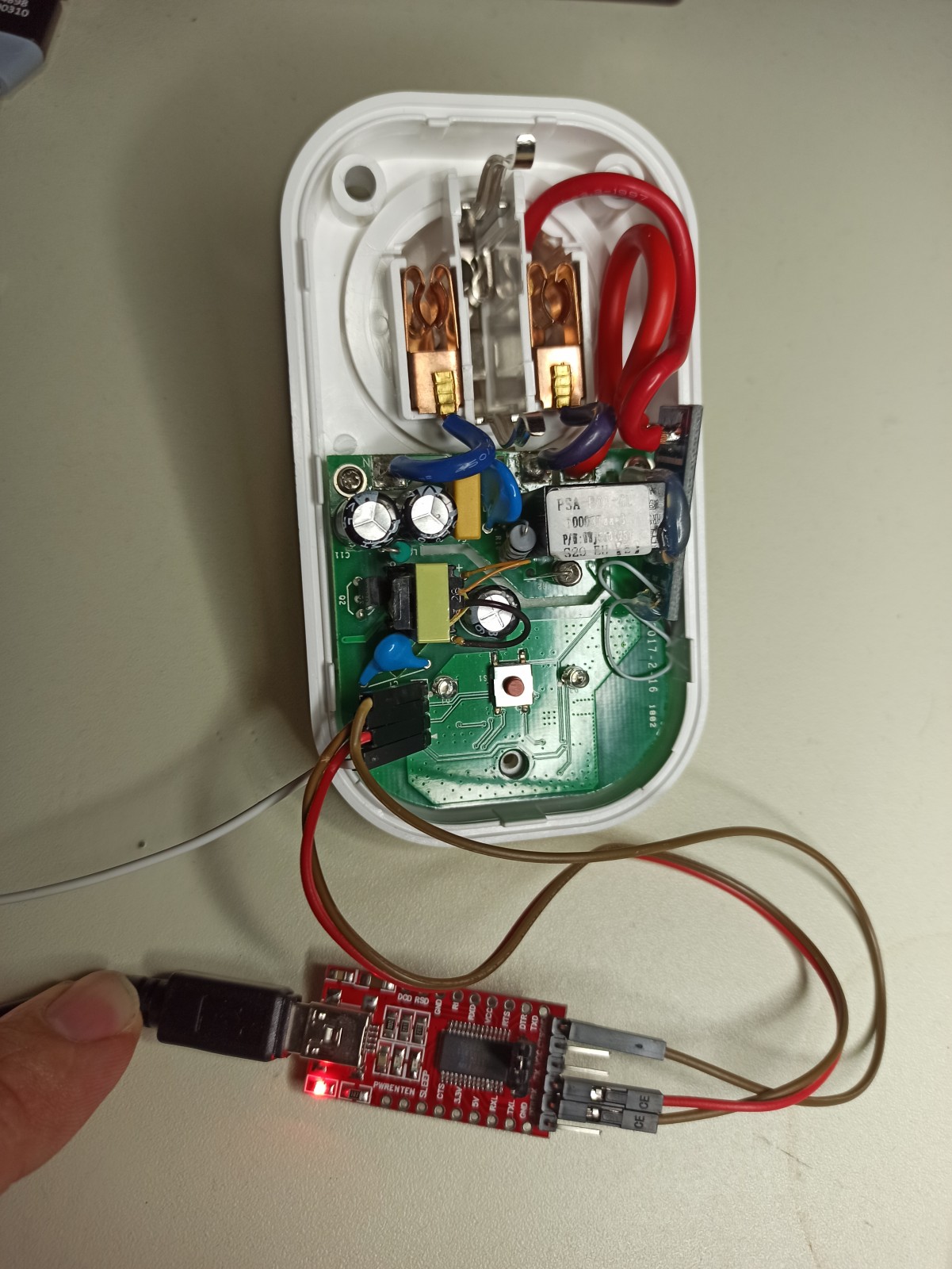
Last thing was to solder the pin header for the UART connector that I’ve used for flashing and debugging the firmware.
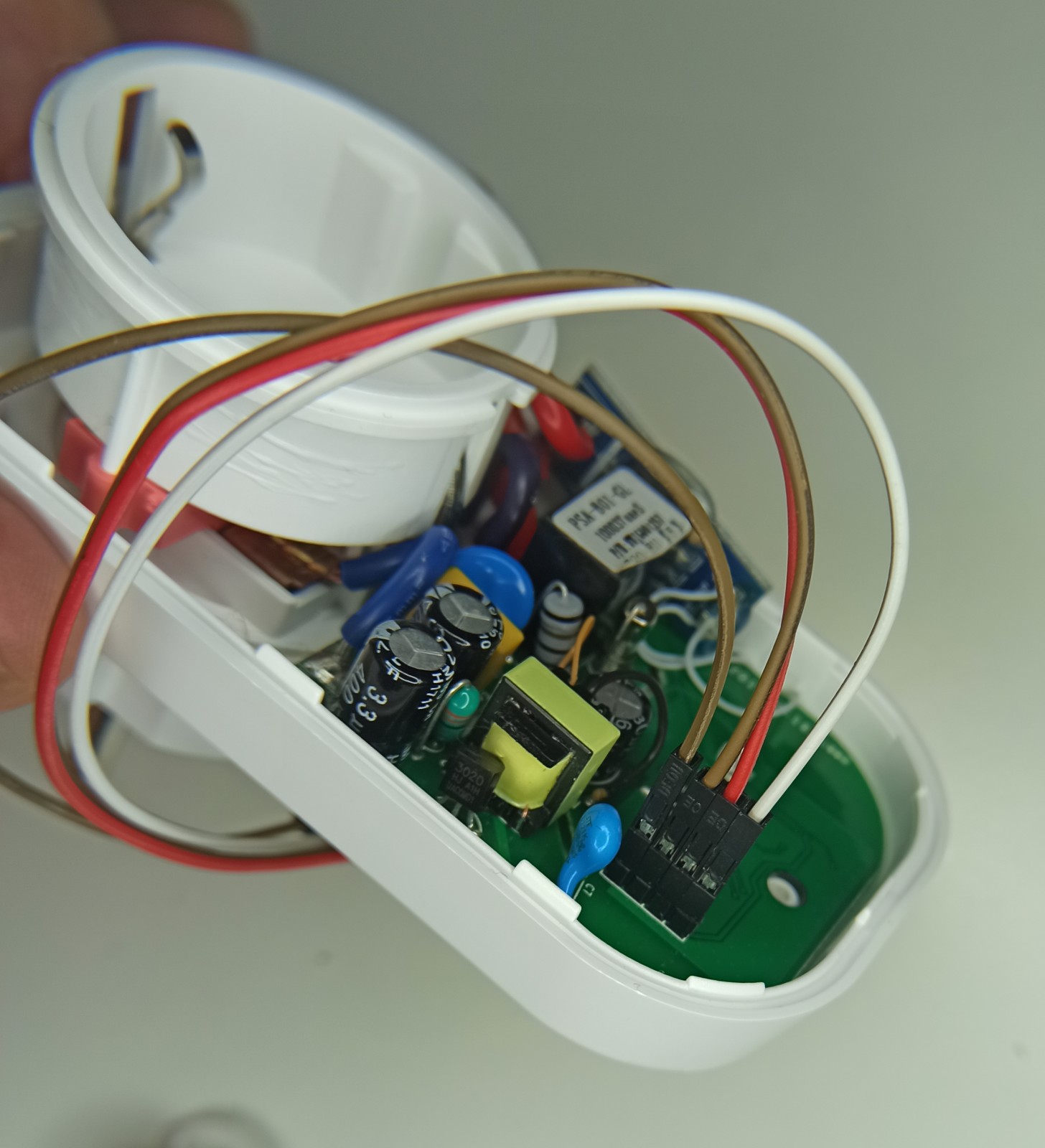
From top to bottom the pinout is GND, TX, RX and VCC. Be aware that if you use the USB-to-UART module to supply the ESP8266 with power then you need to be aware that you need a 3V3 module and not 5V and also never connect the VCC pin of the module while the sonoff device is on the mains. At first I was using the 3V3 of the UART module to flash the device while not connected and then after I’ve verified that everything works as expected, then I’ve removed the VCC from the module and I was flashing the device while it was connected on mains.
So this is the Sonoff before I close the case
And here is with the case closed.
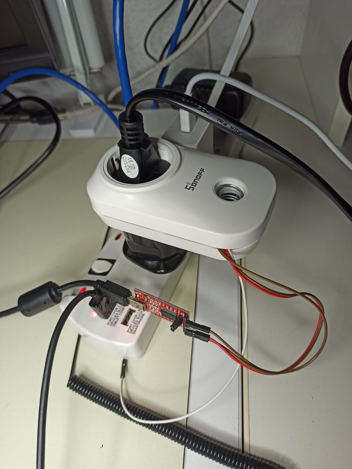
For a test load during my tests I’ve used a hair-dryer which is rated up to 2200W, but it has a cold and heat mode and also different fan and heating modes, so it was easy to test with various currents. Of course, using the hair-dryer’s max power with the ACS712-5A is not a good idea as the dryer can draw up to 10A.
Short firmware description
OK, so now let’s have a look in the source code that I’ve used for testing the ACS712 and the Sonoff. You can find the repo here:
- https://gitlab.com/dimtass/esp8266-sonoff-acs712-test-firmware
- https://github.com/dimtass/esp8266-sonoff-acs712-test-firmware
Reading the ADC value is the easy part, but there are a couple of things that you need to do in order to convert this value to something meaningful. Since I’m measuring AC current, then a snapshot of the ADC value is meaningless as it oscillates around 0V and also takes negative values. In this case we need the RMS value, which is the root-mean-square value. Before continuing further, I’ve compiled this list of equations.
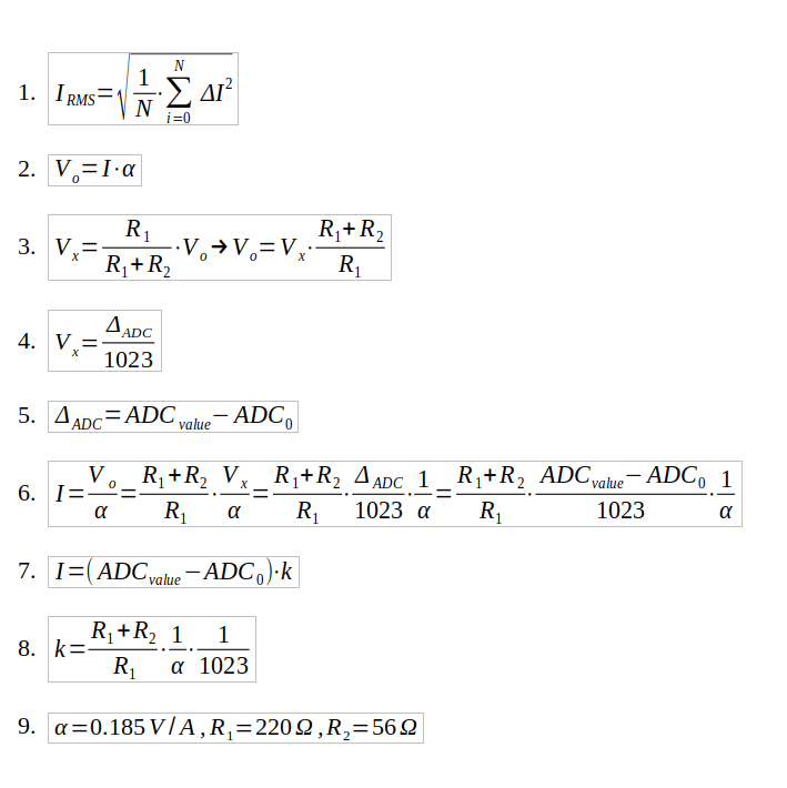
I’m not going to explain everything though, as it’s quite basic equations. (1) is the RMS formula. It’s the square root of the mean of the sum of the sampled square current values. The trick here is that you square the value, therefore that works well for negative values as they add up. Then according to the ACS712 datasheet, in function (2), α is the 185mV/A, which is the sensitivity. This number means that for each Ampere the voltage will change 185mV.
Function (3) is the Vx output of the voltage divider and Vo is the instant value of the ACS712 output. Function (4) states that the Vx is the ADC value divided by 1023. This is true because the max output voltage is 1V and the ADC is 10-bit. Here you also see that, it’s actually the Delta of the ADC value and in (5) you see that the delta is the ADC value minus the ADC0 value.
The ADC0 value is the sampled ADC value of the ACS712 output when there’s no current flowing. Normally, you would expect that to be 511, which is the half of the 1023 max value of the 10-bit ADC, but you need actually to calibrate your device in order to find this value. I’ll explain how to do this later.
In function (6) I’ve just replaced (2) with (3), (4) and (5). Finally, in (7) I’ve replaced the constant values with k, to simplify the equation. In (8) and (9) you can see which are the constant values and their values.
Therefore, in my case k is always 0.026, but I haven’t used a hard-coded value in the code, so in the code you can see from the following that you can change those values to whatever.
1
2
3
4
5
6
7
#define CALIBRATION_VALUE 444
#define ACS712_MVA    0.185   // This means 185mV/A, see the datasheet for the correct value
#define R1            220.0
#define R2            56.0
#define ADC_MAX_VAL   1023.0

float k_const = (1/ADC_MAX_VAL) * ((R1 + R2) / R2) * (1/ACS712_MVA);
Calibration
Now in order to calibrate your device you need to enable the calibration mode in the code.
1
#define CALIBRATION_MODE
First you need to build the firmware and then remove any load from the Sonoff S20. When the firmware starts it will display the ADC sampled value. The code samples the output every 1ms and after 5secs (5000 samples) calculates the average value. This ADC average value is the ADC0 value. Normally, according to the ACS712 datasheet it should be 2.5V, but this may not be always true. This is the output of the firmware in my case
1
2
3
4
5
6
Calibrating with 5000 samples.
Calibration value: 431
Calibration value: 431
Calibration value: 431
Calibration value: 431
Calibration value: 431
Based on that output, I’ve defined the CALIBRATION_VALUE in my code to be 431.
1
#define CALIBRATION_VALUE 431
Testing the firmware
Now, make sure that CALIBRATION_MODE is not defined in the code and re-build and re-flash. After flashing is finished, the green LED is flashing while the Sonoff tries to connect to the WiFi router and when it’s done connecting it stays constant on. By default the relay is always off for safety reasons.
The firmware supports a REST API that it’s used to turn on/off the relay and also get the current Irms value. When the Sonoff is connected to the network, then you can use your browser to control the relay. In the following URLs you need to change the IP address and use the one which is right for your device. To turn the relay on then paste the next URL in your web browser and hit Enter.
1
http://192.168.0.76/relay?params=1
Then you’ll see this response in your browser:
1
{"return_value": 1, "id": "", "name": "", "hardware": "esp8266", "connected": true}
To turn off the relay use this URL:
1
http://192.168.0.76/relay?params=0
Then you’ll get this response from the server (ESP8266)
1
{"return_value": 0, "id": "", "name": "", "hardware": "esp8266", "connected": true}
As you can see, the params variable in the relay URL defines the state of the relay and 0 is OFF and 1 is ON. The return value of the server’s response is the actual value of the relay_status in the code. The REST callback in the code just calls a function that controls the relay and then returns the variable. There’s no a true feedback except the blue LED on the device that the relay is on, so be aware of that. This is the related code:
1
2
3
4
5
6
7
8
9
10
11
12
13
14
15
16
17
18
19
20
int restapi_relay_control(String command);

void SetRelay(bool onoff)
{
  if (onoff) {
    relay_status = 1;
    digitalWrite(GPIO_RELAY, HIGH);
  }
  else {
    relay_status = 0;
    digitalWrite(GPIO_RELAY, LOW);
  }
  Serial.println("Relay status: " + String(relay_status));
}

ICACHE_RAM_ATTR int restapi_relay_control(String command)
{
  SetRelay(command.toInt());
  return relay_status;
}
Finally, you can use the REST API to retrieve the RMS value of the current on the connected load. To do so, browse to this URL
1
http://192.168.0.76/rms_value
The response will be something like this:
1
{"rms_value": 0.06, "id": "", "name": "", "hardware": "esp8266", "connected": true}
As you can see the rms_value field in the response is the RMS current in Amperes. This is the response when the hair dryer is on
1
{"rms_value": 6.43, "id": "", "name": "", "hardware": "esp8266", "connected": true}
As you can see the RMS value now is 6.43A which is more than the 5A limit of the ACS712-5A! That’s not good, I know. Don’t do that. In my case, I’ve only use the high scale of the hair dryer for 1-2 seconds on purpose, which may not be enough to harm the IC. It seems that the overcurrent transient tolerance of the ACS712 is 100A for 100ms, which is quite high, therefore I hope that 6.5A for 2 secs are not enough to kill it.
Last thing regarding this firmware is that the Sonoff button is used to toggle the relay status. The button is using debouncing which is set to 25ms by default, but you can change that in the code here:
1
2
buttons[GPIO_BUTTON].attach( BUTTON_PINS[0] , INPUT_PULLUP  );
buttons[GPIO_BUTTON].interval(25);
Conclusions
In this post, I’ve explained how to hack a Sonoff-S20 smart socket and documented the procedure. You shouldn’t do this if you’re not a trained electronic or electrical engineer, because mains AC can kill you.
To sum up things, I’ve provided a firmware that you can use it to calibrate your ACS712 and the ADC readings and in the normal operation you can also use it to control the relay and read the RMS current value. To switch between modes you need to re-build and re-flash the firmware. The reason for this is just to simplify the firmware and done with is as fast as possible. Of course, it can be done in a way that you can switch between two modes, using the onboard button for example (which is used for toggling the relay by default) or using a REST command. I leave that as an exercise (I really like this moto when people are bored to do things).
As I’ve mentioned this post is just a preparation post for the next one, which will be to use the Sonoff S20 as a node agent that publishes the RMS current and the relay status to a remote Elasticsearch server. Since this hack is out of scope for the next post, I’ve decided to write this one as it’s a quite long process, but also fun.
Normally, I’m using this Sonoff S20 for my 3D printed with a custom REST command to toggle the power from my smartphone or the octopi server that runs on a RPi. I guess that the 3D printer consumption is not that high to get any meaningful data to show, but I’ll try it anyways. Hope you liked the simple hack and don’t do this at home.
Have fun!
Comments powered by Disqus.