WiFi digital control DC power supply with web interface and USB
Intro
Welcome to my next stupid project!
Ok, this project is really stupid and I’ll probably never going to use it for any of my next projects, but it was fun doing it nevertheless. I have a bunch of these adjustable LM2596 DC-DC boards in one of my magic component cabinets, that you can find quite cheap in ebay (~$1.5).
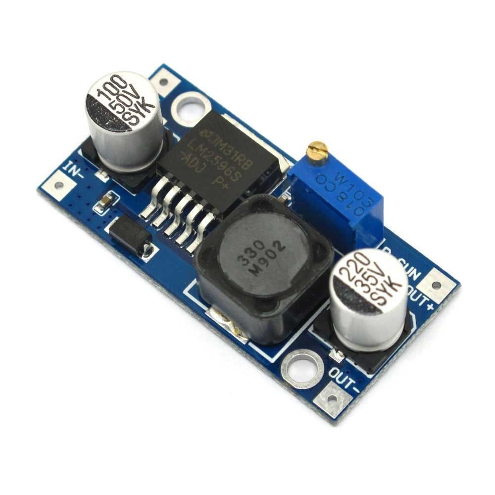
As you can see it’s composed of few components like an inductor, capacitors, resistors e.t.c. You apply a DC input voltage and then you get a step-down DC output on the other side. You can control the output voltage with a 10KΩ pot (the blue block device with the screw on top). That’s great. But… this means that every time you need to change the output voltage you need to turn the screw several times to get it. The good thing with that is that if you have a good multimeter you can get quite precise output voltages as the POT is analog. The bad thing is that you need to do manual labor every time you need to change the output voltage. But not anymore.
The idea was to simply change the analog POT with a digital one and then find a way to control it remotely. So, why not do that using a UART port, or even better a USB port. Oh, wait… Why not make it WiFi controlled and also have a web interface? And this how stupid projects are made. Do to that we’ll need the following components.
Components
Digi-pot
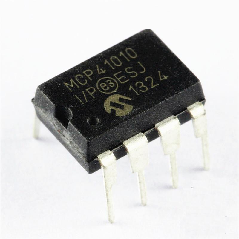
There are several digital pots on the ebay and they are cheap, but the trick here is to find a digi-pot that has enough wiper points (or steps). Why you need many steps? The step for a digital pot defines it’s resolution, so for a 10KΩ pot with 100 steps (like the X9C103P each step is 10ΚΩ/100=100Ω. That’s quite large when it’s used in voltage a divider like the pot on the LM2596 board. On the other hand by using a digi-pot like the MCP41010 that has 256 steps, the resolution gets much higher. You can find these microchip digi-pots on ebay for around $1.5 each.
The mcp41010 is controlled with an SPI interface, which means that you need a micro-controller. That’s cool, because this means that you can also use an ESP8566 wifi module and why not a USB interface if the controller comes with it
Micro-controller
I like ARM processors. My favorite boards are those stm32f103c8t6 that you can find on ebay for $2. They are ultra-cheap, they have almost any interface that I need for my stupid projects and they also have a very nice API to program them. The stm32f103 has a USB port, more than the 2 uarts that are needed and an SPI interface to control the digi-pot.
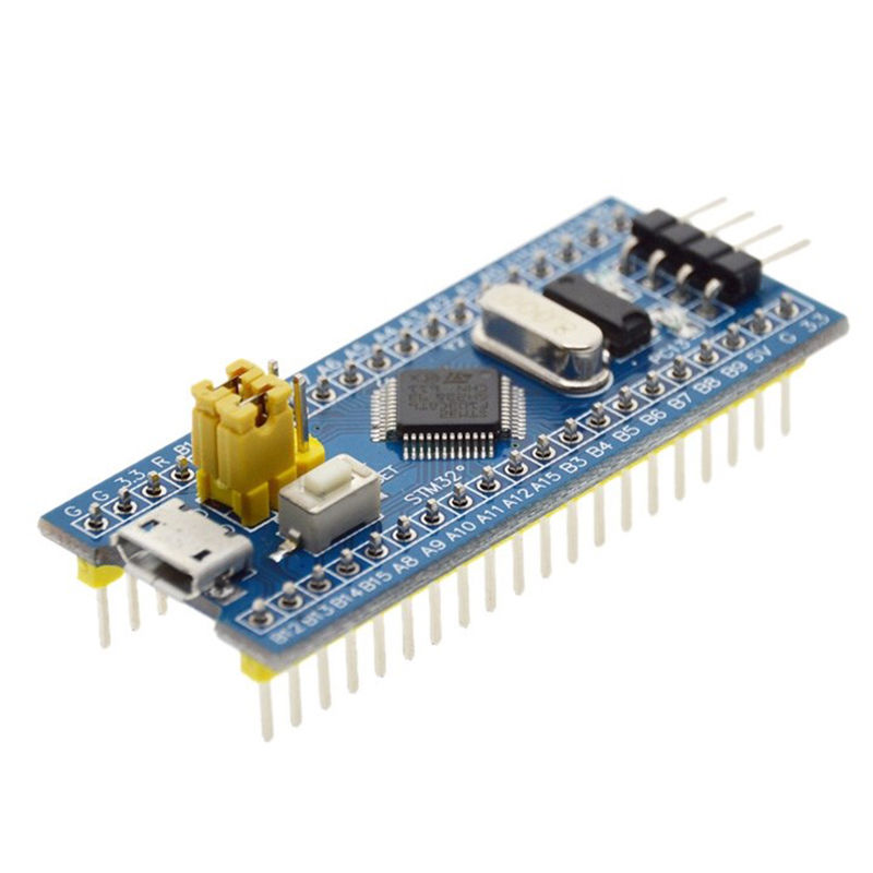
This board is power either from the USB connector either from the 5V or 3.3V on-board pins. Never use both of them at the same time!
ESP8266
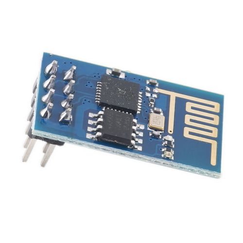
The ESP8266 shows up again on this stupid project as also on the first one. Copy-paste from the previous post follows: it’s easy to modify the source code with the SDK and also you can use any network capable device to interact with them. I’ll write a separate post about ESP8266 in the future and how you can write your own code for these modules. You can find them cheap in ebay and they cost around $2.50. There are a few types of this module that they have a different flash size (512KB, 1MB), but the only thing that you should care about now is that it needs to support 9600 baud rate and not only 115200, because I’m using a software serial library for the arduino that behaves much better on lower baud rates. Be aware that ESP8266 is a 3V3 only device. This is the module:
Output relay
In the output I’ve used a relay to turn on and off the output from the LM2596, you may not want to do that, but it’s nice to have it. There are many cheap variations of opto-couple relays in ebay that cost $1-$2 like this one
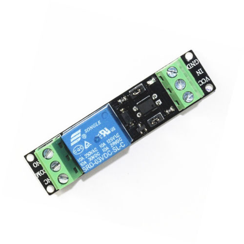
I prefer the high-level drive relays as the microprocessors usually after a reset they drive their pins to low, which is safe as the relay doesn’t get activated when the mcu is reset. You can connect the positive voltage output of the reference power supply to the COM and NC terminals. Also, make sure that the relay is rated for the DC output you’re going to use, so don’t use a 30V relay to output 40V. Finally, make sure that the relay is able to be activated with a 3V3 input trigger.
Step-down (AMS1117-3.3)
You’ll also need a step-down DC power supply module to power the components, like the AMS1117-3.3. There are some cheap pre-soldered modules with the AMS1117 on the ebay, I’ve found 5pcs for less that $1, which means $0.20 for each. They look like this
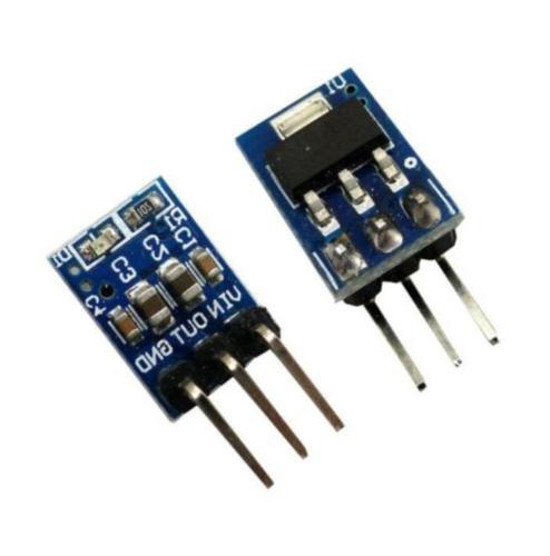
They are very convenient if you are using a breadboard or a double-sided prototype PCB, as they only have 3 pins and all the needed components are on the module. It also has a LED indicator that indicates that it’s powered.
Prototype breadboard
If you want to assembly the circuit without design a PCB, then you can buy on ebay one of these cheap prototype breadboards for less than $1.
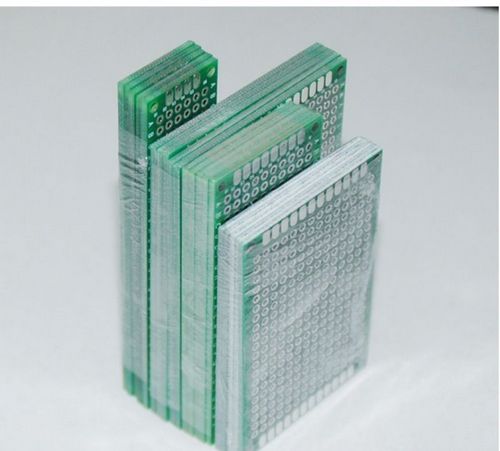
The image is from a pack of various pcb sizes, you’ll just need one that fits everything you need to solder.
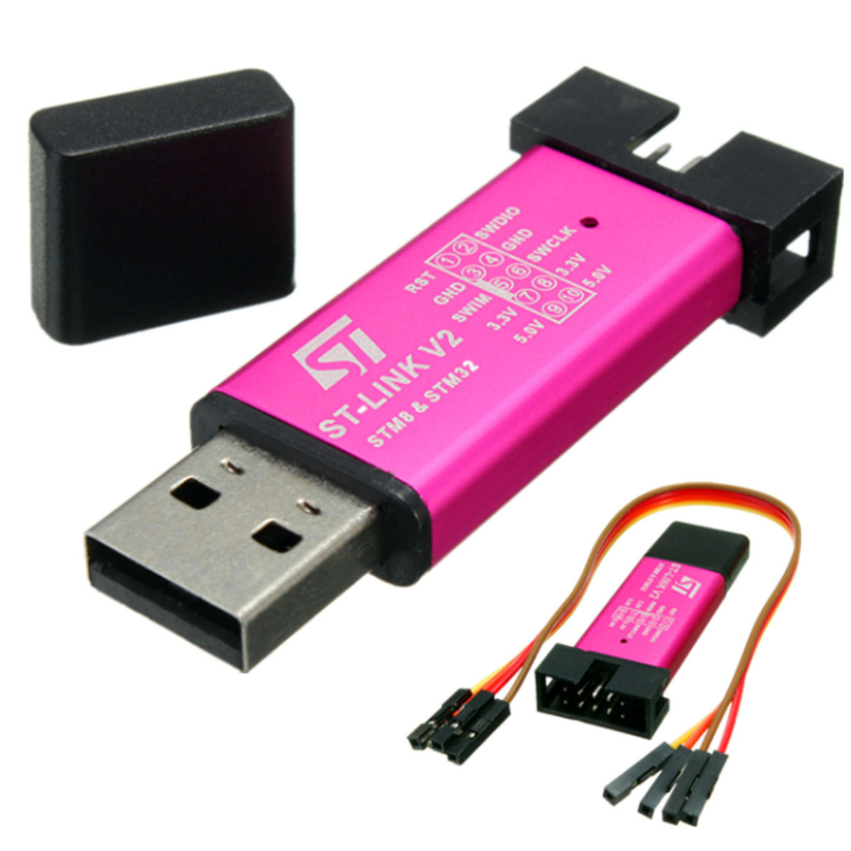
ST-Link
Finally, you need an ST-Link programmer to upload the firmware. Generally, I have the original ST-Link V2 and the Segger J-link programmers, but to be honest, most of the times I’m using one of these cheap st-link copies; which I find much more convenient to use on the limited workspace. Of course, I suggest you to buy the original ones, but if you also have a limited space then buy one of those from ebay.
Making the stupid project
I haven’t build a PCB for this project and it is only a proof of concept on my breadboard. These are the schematics of the circuit you need to build.
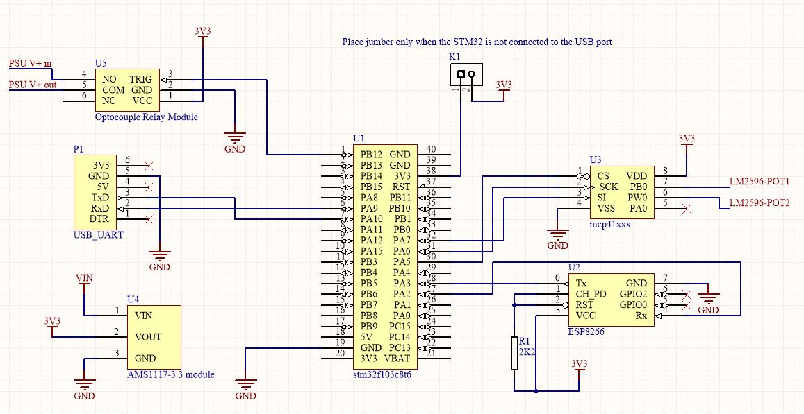
The stm32 is powered either from the USB port when it’s connected on the PC or from the AMS1117-3.3. Therefore, you need to be careful with that, so if you’re going to use a USB adapter or connect the stm32 to your PC then you need to remove the K1 jumper. If you’re not going to use the USB interface then place the jumper.
When you unsolder the blue resistor POT from the LM2596 PSU module, then you’ll have three empty holes on the PCB. The LM2596-POT1 and LM2596-POT2 terminals are connected to the PCB holes next to the OUT+ output. There are two main power inputs, the one is the VIN that is connected to the AMS1117-3.3 and provides power to the circuit and the other is the PSU V+ that comes from the external power supply you’re going to use for the LM2596. Therefore, the LM2596-POT1/2 and PSU V+ in/out are connected to the LM2596 PSU. The USB_UART (P1) is not necessary to use and it’s just the debug UART port.
You can download the source files from my github project
https://github.com/dimtass/stm32f103-wifi-usb-psu
Read the README.md file as it has all the details you need, but still I’ll explain some things here. You don’t have to build the code to use it, but I suggest that you do as you need to change a few parameters in the source files. The pre-build binaries of the latest build are located in the firmware folder, therefore you can use the ST-Link utility on windows to flash the hex file or the st-flash utility on Linux to flash the bin file. To upload the firmware you just need to connect the USB cable on the stm32f103 board and run the flashing commands which are in the README.md file.
If you need to build the code then you’ll find the cmake files and scripts for both Windows and Linux. So, if you have a Windows OS, then you need to install cmake, make and a gcc toolchain for the ARM cortex-M3. Read this to see how you can do that.
After you’ve setup everything, all you need to do is run the build.cmd (on Windows) or build.sh (on Linux) to build the code. Cmake will create the binaries in the build-stm/src folder but also will create the .cproject and .project files in the build-stm folder. This means that you can import this project to your eclipse CDT IDE and edit the code in there.
One of the things you probably have to edit is the IP address definition HTTP_IP_ADDRESS in the src/http_server.h file. This is the address that your AP assigns to the ESP8266 module. That means that you need to configure your AP router to always assign the same IP to the MAC address of the ESP8266. Then you can re-build the code and flash the new binary on the stm32. It’s recommended to erase the stm32’s flash before you upload the firmware as the last 1K of the flash (address: 0x0800FC00) is used to store the configuration data, like the AP SSID, password and the pre-defined POT values.
The first time that the stm32 powers up after a firmware update, it will try to load the configuration data from the flash. If it doesn’t find a valid configuration then it creates a default configuration. In the default configuration the stm is not able to connect to any AP and the pre-defined POT values are all set to 127 (which means 5KΩ). You can use the USB or UART interface to update the configuration data for the AP SSID and password. To do that just connect the stm via a USB cable on your computer and open a terminal (I always prefer to use Bray’s terminal. Whatever terminal you use make sure that the LF char is handled as (CR & LF). Bray’s terminal has that option by checking the CR=LF checkbox in the settings area and the +CR next to the -> Send button.
If you have already red the README.md file in the project folder you’ll know which commands to use. As an example I’ll suppose that the AP SSID name is Router and the WPA2 password is MyPassword; of course, you need to change these with your own. To update the configuration send the following commands to the terminal.
1
2
3
SSID=Router
PASS=MyPassword
RECONNECT
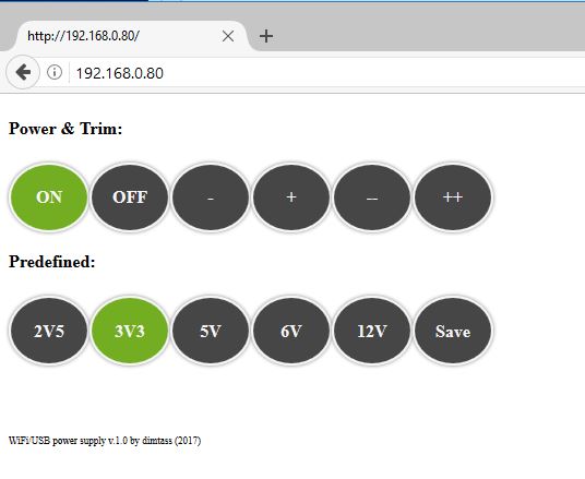
The first command stores the SSID name, the second the password and the third one initiates a reconnection to the router. If the last one doesn’t work, just remove and re-apply the power on the stm. When the stm starts then the LED will start flashing every 250ms if the ESP is not connected and when it gets connected the it flash every 500ms. When it’s connected you can finally open you browser and connect to the web interface by writing its IP address on the address bar. This is what you’ll get

This is a very simple html page, so there are minimal javascript automations, which means that the web interface will not automatically restore the PSU state, so you don’t really know if it’s turned on/off and which pre-defined output is used. Therefore, have that in mind. On some browsers you may need to do a dummy click on a button first, so you can click the OFF button for 1-2 times. As you see the web interface is quite simple. In the first row there are the Power & Trim buttons that you use to turn off or on the output relay and trim the output voltage by change the digi-pot value. The +/- buttons change the digi-pot step by 1 on every click and the ++/-- buttons change the step by 5. You’ll need these buttons to trim the output and save the value on one of the pre-defined values.
Let’s say that it’s the first time you open the web interface after a new firmware update and a full flash erase, so there aren’t any configuration data. Also suppose that you’ve chosen that the pre-defined values will be (2V5), (3V3), (5V), (6V) and (12V) in the src/http_server.c file. Now you need to do the calibration procedure as all the pre-defined values are set by default to step 127 for the digi-pot (5KΩ). First connect the input power ΙΝ+/ΙΝ- to the LM2596 (e.g. 12V) and a multimeter in the output to measure the voltage, then click 1-2 times the OFF button, click the pre-defined value you need to set and click the ON button. On your multimeter you’ll see the output value that corresponds to the digi-pot’s step 127 (5KΩ). Now you need to change the output. To do that keep pressing the (--) button (or ++) until you get as close to the pre-defined value. Then use the (-/+) buttons to trim further and get the wanted output. Don’t expect the output to be very precise as the 256 steps for a 10K digi-pot is only 39Ω per step. When you get the nearest value to the wanted one then press the (Save) button and this value will be stored. Then press the next pre-defined button (3V3) and repeat the procedure until you set all the values and this is how the calibration is done. Don’t expect to get 12V in the output with a 12V input as there’s about a 0.7V drop on the LM2596.
The digi-pot is a linear resistor and not logarithmic like the pot you’ve replaced on the LM2596. This means that if you use a 12V PSU as a reference, you’ll get a better resolution under the 5V but over this voltage the resolution drops significantly.
If for some reason you change the input voltage on the LM2596 then you need to repeat the calibration procedure again. Also, it’s good to do that from time to time to be sure that it’s calibrated and always check the output with a multimeter before you connect a circuit. If you need another output voltage then just connect your multimeter in the output press the pre-defined voltage that’s closer to the wanted output and use the (+/-) button to get it.
Finally, you can do all these things by using the USB connection and the commands that are explained in the README.md file. You can also use the USB interface to set the exact digi-pot step value like this.
1
POT=127
You can set any value from 0 to 255.
This is a screenshot of how the web interface actually looks like in use.
You can edit the html file in the src/http_server.c source code file. You can right click on you browser and view the page source as it’s quite cryptic with the C formatting and then you can do any changes you like. Just don’t add too many things in there because the interface will take more time to load. You can change the CSS styles also to change the colors and then re-build the code and upload the firmware.
Summary
Well, this is a completely stupid project and is quite simple to build. All the needed components costs around $10. This the list of the components and their approximate price on ebay (you may find these even cheaper).
| Part | Price |
|---|---|
| LM2596 PSU | ~ $1.5 |
| MCP41010 (10KΩ digi-pot) | ~ $1.5 |
| STM32F103C8T6 dev board | ~ $2 |
| ESP8266-05 module | ~ $2.5 |
| Optocouple relay board | ~ $1.5 |
| AMS1117-3.3 module | ~ $0.20 |
| double sided prototype breadboard | ~ $1 |
This is an extremely bad photo of everything working on a breadboard.
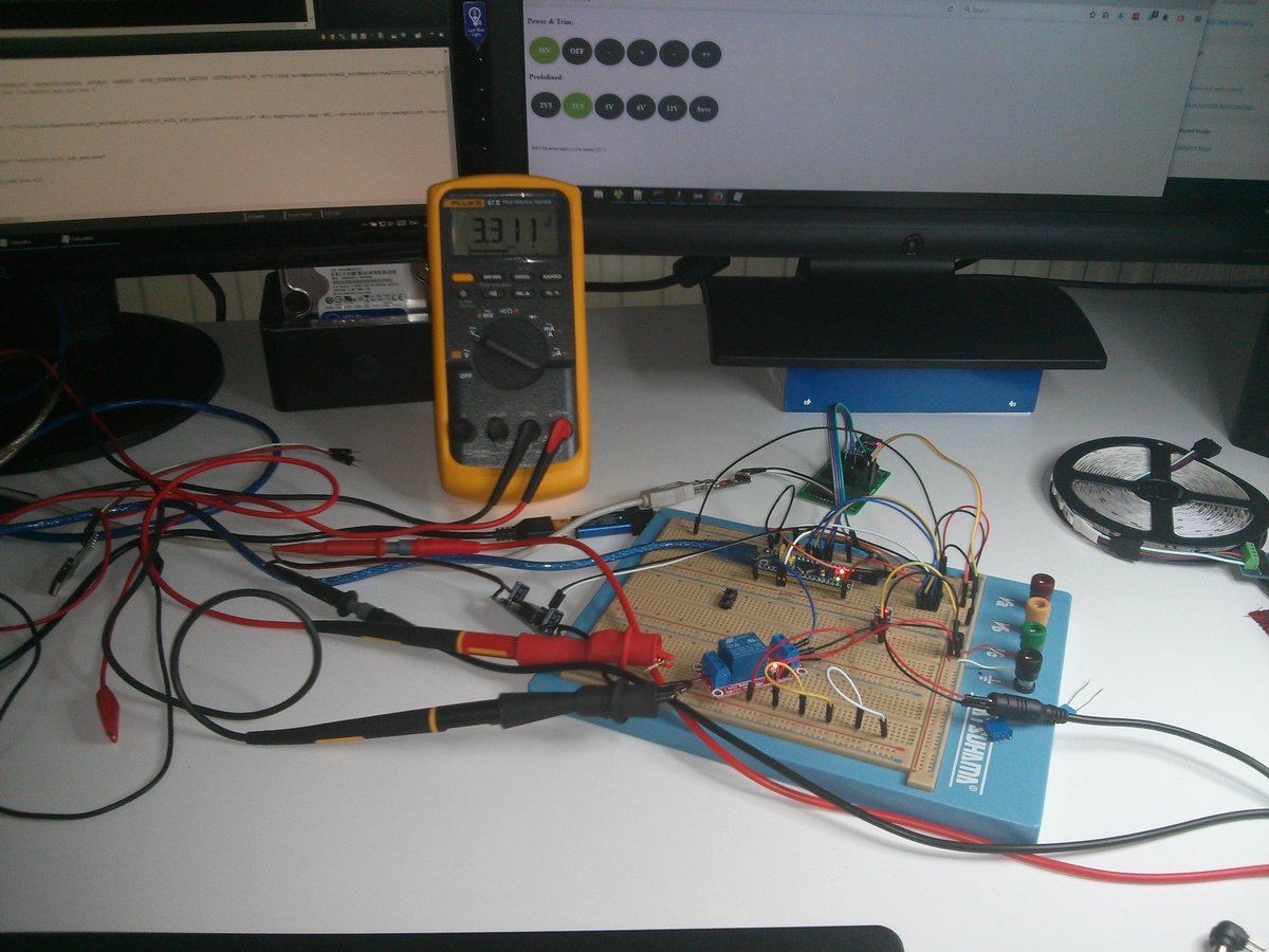
Have fun!
Comments powered by Disqus.